AUDIO AND VISUAL SYSTEM(for Radio and Display Type) Vehicle Speed Signal Circuit between Radio Receiver and Combination Meter
DESCRIPTION
The radio and display receiver assembly receives a vehicle speed signal from the combination meter assembly to control the ASL function.
Tech Tips
-
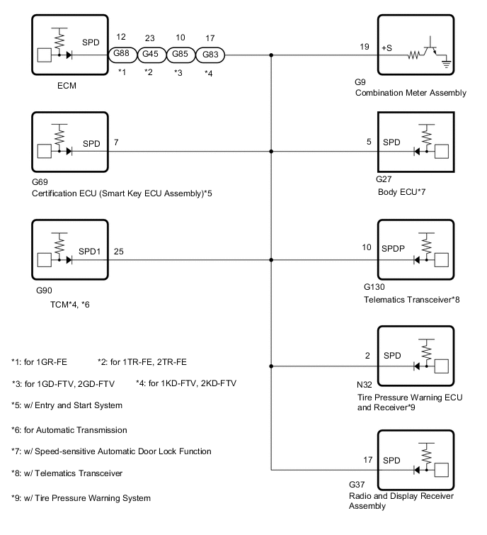
A voltage of 12 V or 5 V is output from each ECU and then input to the combination meter assembly. The signal is changed to a pulse signal at the transistor in the combination meter assembly. Each ECU controls its respective system based on this pulse signal.
-
If a short occurs in any of the ECUs or in the wire harness connected to an ECU, all systems in the diagram below will not operate normally.
WIRING DIAGRAM
CAUTION / NOTICE / HINT
Note
Check that the wire harness is properly installed and does not have any sharp bends, pinching or loose connections.
PROCEDURE
-
CHECK COMBINATION METER ASSEMBLY (OUTPUT WAVEFORM)
-
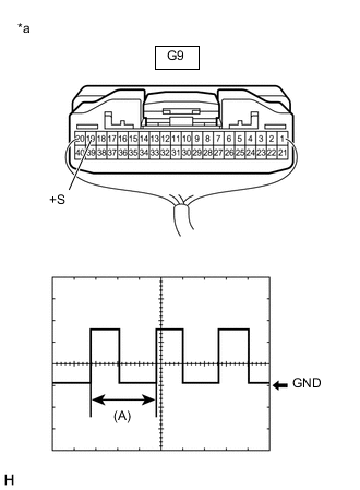
*a Component with harness connected
(Combination Meter Assembly)
Check the output waveform.
-
Remove the combination meter assembly with the connector still connected.
-
Connect an oscilloscope to terminal G9-19 (+S) and body ground.
-
Turn the ignition switch to ON.
-
Turn a wheel slowly.
-
Check the signal waveform according to the condition(s) in the table below.
Item Condition Measurement terminal G9-19 (+S) - Body ground Tool setting 5 V/DIV, 20 ms./DIV Vehicle condition Wheel being rotated OK The waveform is similar to that shown in the illustration. Tech Tips
When the system is functioning normally, one wheel revolution generates 4 pulses. As the vehicle speed increases, the width indicated by (A) in the illustration narrows.
Result Proceed to OK NG -
NG 
GO TO METER / GAUGE SYSTEM Click here
OK 
-
-
CHECK HARNESS AND CONNECTOR (RADIO AND DISPLAY RECEIVER ASSEMBLY - COMBINATION METER ASSEMBLY)
-
*1: for 1GR-FE
-
*2: for 1TR-FE, 2TR-FE
-
*3: for 1GD-FTV, 2GD-FTV
-
*4: for 1KD-FTV, 2KD-FTV
-
*5: w/ Entry and Start System
-
*6: w/ Speed-sensitive Automatic Door Lock Function
-
*7: for Automatic Transmission
-
*8: w/ Telematics Transceiver
-
*9: w/ Tire Pressure Warning System
-
Disconnect the G37 radio and display receiver assembly connector.
-
Disconnect the G9 combination meter assembly connector.
-
Disconnect the G88*1, G45*2, G85*3 or G83*4 ECM connector.
-
Disconnect the G69 certification ECU (smart key ECU assembly) connector.*5
-
Disconnect the G27 body ECU connector.*6
-
Disconnect the G90 TCM connector.*4, *7
-
Disconnect the G130 telematics transceiver connector.*8
-
Disconnect the N32 tire pressure warning ECU and receiver connector.*9
-
Measure the resistance according to the value(s) in the table below.
Standard Resistance Tester Connection Condition Specified Condition G37-17 (SPD) - G9-19 (+S) Always Below 1 Ω G37-17 (SPD) or G9-19 (+S) - Body ground Always 10 kΩ or higher Result Proceed to OK NG
OK
PROCEED TO NEXT SUSPECTED AREA SHOWN IN PROBLEM SYMPTOMS TABLE Click here
NG
REPAIR OR REPLACE HARNESS OR CONNECTOR
-