МАСЛЯНЫЙ НАСОС УСТАНОВКА
-
INSTALL TIMING CHAIN COVER OIL SEAL
-
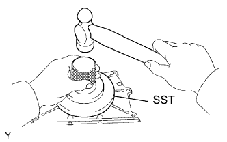
Using SST and a hammer, tap in a new oil seal until its surface is flush with the rear oil seal retainer edge.
- SST
- 09223-78010
-
Apply MP grease to the oil seal lip.
-
-
INSTALL TIMING CHAIN COVER
-
Remove any old seal packing (FIPG material) and be careful not to drop any oil on the contact surfaces of the timing chain cover, cylinder head and cylinder block.
-
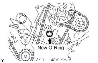
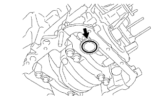
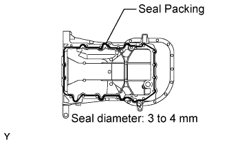
Install a new O-ring to the cylinder head LH as shown in the illustration.
-
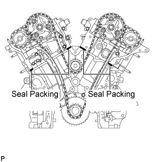
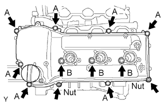
Apply seal packing as shown in the illustration.
Seal packing Toyota Genuine Seal Packing Black, Three Bond 1207B or equivalent Standard seal diameter 3.5 to 4.5 mm (0.14 to 0.18 in.) -
Apply seal packing in a continuous line to the timing chain cover as shown in the illustration.
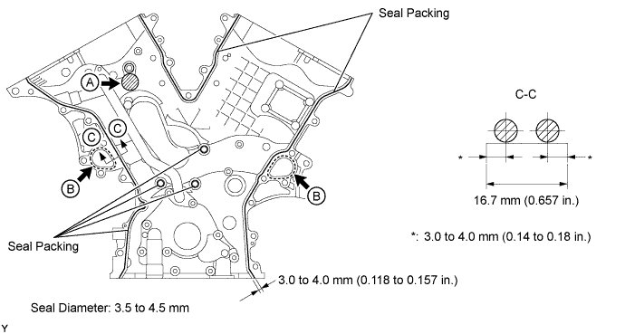
Seal packing for water related parts labeled "B" Toyota Genuine Seal Packing 1282B, Three Bond 1282B or equivalent for oil related parts Toyota Genuine Seal Packing Black, Three Bond 1207B or equivalent Standard seal diameter 3.5 to 4.5 mm (0.14 to 0.18 in.) Note
-
Install the timing chain cover within 3 minutes after applying seal packing. After installing the timing chain cover, the timing chain cover bolts and nuts must be tightened within 15 minutes. Otherwise the seal packing must be removed and reapplied.
-
Do not apply seal packing to the position labeled "A" shown in the illustration.
-
-
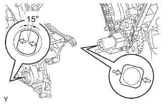
Align the hole of the oil pump drive rotor with the rectangular portion of the crankshaft timing sprocket, and slide the timing chain cover into place.
-
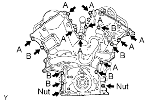
Install the timing chain cover with the 15 bolts and 2 nuts. Uniformly tighten the bolts and nuts in several passes.
- Torque:
- 23 N*m { 235 kgf*cm, 17 ft.*lbf }
Note
Do not allow any seal packing to contact the chain and slipper when installing the timing chain cover.
Tech Tips
Each bolt length is as follows:
A: 25 mm (0.98 in.)
B: 55 mm (2.17 in.)
-
-
INSTALL OIL FILTER BRACKET
-
Install a new gasket and the oil filter bracket with the 3 bolts and 2 nuts.
- Torque:
- 19 N*m { 194 kgf*cm, 14 ft.*lbf }
-
-
INSTALL VVT SENSOR
-

Install the sensor with the bolt.
- Torque:
- 8.0 N*m { 82 kgf*cm, 71 in.*lbf }
-
Connect the sensor connector.
-
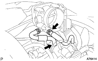
Connect the No. 4 and No. 5 water by-pass hoses.
-
-
INSTALL CYLINDER HEAD COVER LH
-
Remove any old packing (FIPG) material and be careful not to drop any oil on the contact surfaces of the cylinder head, timing chain cover and cylinder head cover.
-
Apply adhesive on the threads of the ventilation valve.
Adhesive Toyota Genuine Adhesive 1324, Three Bond 1324 or equivalent -
Install the ventilation valve to the cylinder head cover.
- Torque:
- 27 N*m { 275 kgf*cm, 20 ft.*lbf }
-
Install the gasket to the cylinder head cover.
-
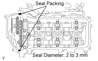
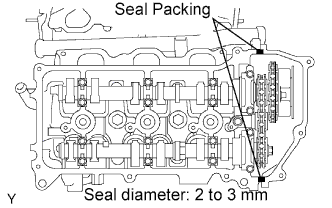
Apply a continuous bead of the seal packing to the cylinder head and timing chain cover as shown in the illustration.
Seal packing Toyota Genuine Seal Packing Black, Three Bond 1207B or equivalent Seal diameter 2 to 3 mm (0.08 to 0.12 in.) Note
Install the cylinder head cover within 3 minutes after applying seal packing. After installing it, cylinder head cover bolts and nuts must be tightened within 15 minutes. Otherwise the seal packing must be removed and reapplied.
-
Install the seal washers to the bolts.
-
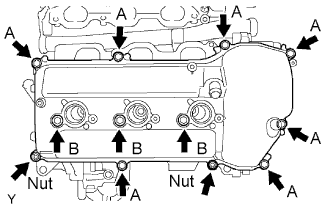
Install the cylinder head cover with the 10 bolts and 2 nuts. Uniformly tighten the bolts and nuts in several passes.
- Torque:
- 10 N*m { 102 kgf*cm, 7 ft.*lbf, for bolt A }
- 9.0 N*m { 92 kgf*cm, 80 in.*lbf, for bolt B }
- 9.0 N*m { 92 kgf*cm, 80 in.*lbf, for nut }
-
-
INSTALL CYLINDER HEAD COVER RH
-
Remove any old packing (FIPG) material and be careful not to drop any oil on the contact surfaces of the cylinder head, timing chain cover and cylinder head cover.
-
Install the gasket to the cylinder head cover.
-
Apply a continuous bead of the seal packing to the cylinder head and timing chain cover as shown in the illustration.
Seal packing Toyota Genuine Seal Packing Black, Three Bond 1207B or equivalent Seal diameter 2 to 3 mm (0.08 to 0.12 in.) Note
Install the cylinder head cover within 3 minutes after applying seal packing. After installing it, cylinder head cover bolts and nuts must be tightened within 15 minutes. Otherwise the seal packing must be removed and reapplied.
-
Install the seal washers to the bolts.
-
Install the cylinder head cover with the 10 bolts and 2 nuts. Uniformly tighten the bolts and nuts in several passes.
- Torque:
- 10 N*m { 102 kgf*cm, 7 ft.*lbf, for bolt A }
- 9.0 N*m { 92 kgf*cm, 80 in.*lbf, for bolt B }
- 9.0 N*m { 92 kgf*cm, 80 in.*lbf, for nut }
-
-
INSTALL IGNITION COIL
-
Install the 6 ignition coils with the 6 bolts.
- Torque:
- 10 N*m { 102 kgf*cm, 7 ft.*lbf }
-
-
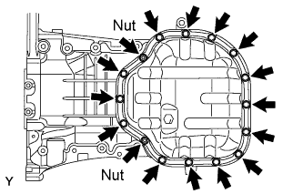
INSTALL NO. 1 OIL PAN
-
Remove any old seal packing (FIPG material) and be careful not to drop any oil on the contact surfaces of the cylinder block, rear oil seal retainer and oil pan.
-
Install a new O-ring to the oil pump.
-
Apply seal packing in a continuous line as shown in the illustration.
Seal packing Toyota Genuine Seal Packing Black, Three Bond 1207B or equivalent Seal diameter 3 to 4 mm (0.12 to 0.16 in.) Note
-
Remove any oil from the contact surface.
-
Install the oil pan within 3 minutes after applying seal packing. After installing the oil pan, the oil pan bolts and nuts must be tightened within 15 minutes. Otherwise the seal packing must be removed and reapplied.
-
Do not start the engine for at least 4 hours after the installation.
-
-
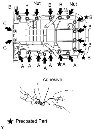
Install the oil pan with the 17 bolts and 2nuts. Uniformly tighten the bolts and nuts in several passes.
- Torque:
- 21 N*m { 214 kgf*cm, 15 ft.*lbf, for bolt A }
- 21 N*m { 214 kgf*cm, 15 ft.*lbf, for bolt B }
- 10 N*m { 102 kgf*cm, 7 ft.*lbf, for bolt C }
- 21 N*m { 214 kgf*cm, 15 ft.*lbf, for nuts }
Tech Tips
Each bolt length is as follows:
A = 25 mm (0.98 in.)
B = 45 mm (1.77 in.)
C = 14 mm (0.55 in.)
Note
The bolts indicated by stars in the illustration are precoated parts. When reusing these bolts, apply adhesive to 2 or 3 threads before installation.
Adhesive Toyota Genuine Adhesive 1324, Three Bond 1324 or equivalent
-
-
INSTALL OIL STRAINER
-
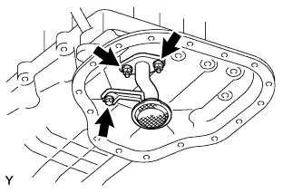
Install a new gasket and the oil strainer with bolt and 2 nuts.
- Torque:
- 9.0 N*m { 92 kgf*cm, 80 in.*lbf }
-
-
INSTALL NO. 2 OIL PAN
-
Remove any old seal packing (FIPG material) and be careful not to drop any oil on the contact surfaces of the oil pan and No. 2 oil pan.
-
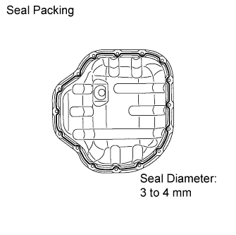
Apply seal packing in a continuous line as shown in the illustration.
Seal packing Toyota Genuine Seal Packing Black, Three Bond 1207B or equivalent Seal diameter 3 to 4 mm (0.12 to 0.16 in.) Note
-
Remove any oil from the contact surface.
-
Install the No. 2 oil pan within 3 minutes after applying seal packing. After installing the oil pan, the oil pan bolts and nuts must be tightened within 15 minutes. Otherwise the seal packing must be removed and reapplied.
-
Do not start the engine for at least 4 hours after the installation.
-
-
Install the No. 2 oil pan with the 14 bolts and 2 nuts. Uniformly tighten the bolts and nuts in several passes.
- Torque:
- 9.0 N*m { 92 kgf*cm, 80 in.*lbf, for bolts }
- 10 N*m { 102 kgf*cm, 7 ft.*lbf, for nuts }
-
-
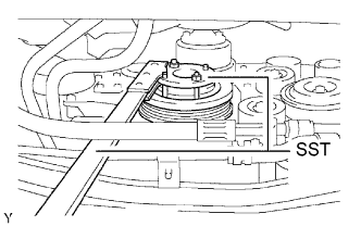
INSTALL CRANKSHAFT PULLEY
-
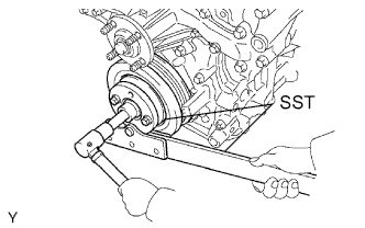
Using SST, install the pulley set bolt.
- SST
- 09213-54015 ( 91651-60855 )
- 09330-00021
- Torque:
- 250 N*m { 2,549 kgf*cm, 184 ft.*lbf }
-
-
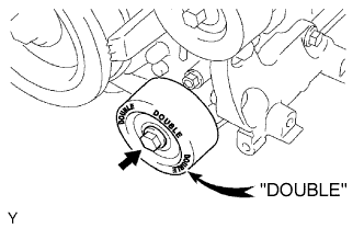
INSTALL NO. 1 IDLER PULLEY
-
Установите опорный шкив, закрепив его болтом.
- Torque:
- 54 Н*м { 551 кгс*см, 40 фунт-сила-футов }
Tech Tips
На опорный ролик № 1 нанесена маркировка "DOUBLE", позволяющая отличить его от опорного ролика № 2.
-
-
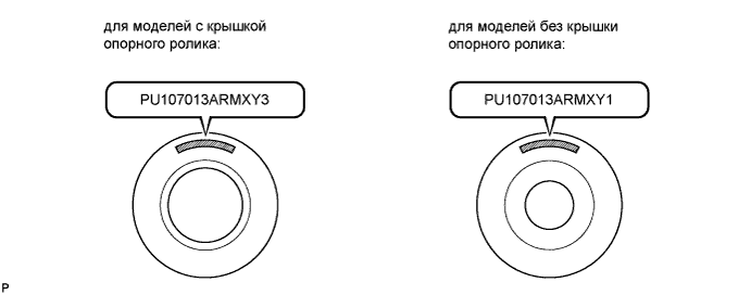
INSTALL NO. 2 IDLER PULLEY
Note
Для опорных роликов со съемными крышками:
Установка опорных роликов № 2 зависит от нанесенной на них маркировки, показанной на рисунке.
Tech Tips
Выполните эту же операцию для обоих опорных роликов № 2.
-
Для опорных роликов с крышкой (PU107013ARMXY3):
-
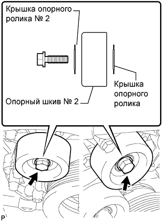
Установите крышку опорного ролика, опорный ролик и крышку опорного ролика № 2 и закрепите их болтом.
- Torque:
- 54 Н*м { 551 кгс*см, 40 фунт-сила-футов }
Note
-
Если необходимо заменить ролик или любую крышку, замените крышку опорного ролика № 2, опорный ролик № 2 и крышку опорного ролика комплектом новых деталей.
-
Заменяя детали, проследите, чтобы новый опорный ролик № 2 имел маркировку "PU107013ARMXY3".
-
-
Для опорных роликов без крышки (PU107013ARMXY1):
-
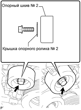
Установите опорный ролик и закрепите крышку опорного ролика № 2 болтом.
- Torque:
- 54 Н*м { 551 кгс*см, 40 фунт-сила-футов }
Note
-
Если необходимо заменить ролик или крышку, замените ролик вместе с крышкой на комплект новых деталей, состоящий из крышки опорного ролика № 2, опорного ролика № 2 и крышки опорного ролика.
-
Заменяя детали, проследите, чтобы новый опорный ролик № 2 имел маркировку "PU107013ARMXY3".
-
-
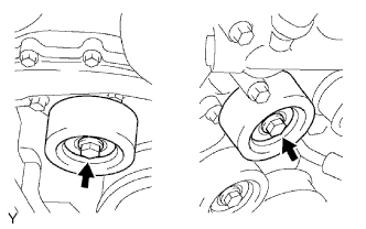
Для интегрированного типа:
Установите 2 опорных ролика № 2 и закрепите их 2 болтами.
- Torque:
- 54 Н*м { 551 кгс*см, 40 фунт-сила-футов }
-
-
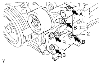
INSTALL V-RIBBED BELT TENSIONER
-
Временно установите натяжитель поликлинового ремня и закрепите его 5 болтами.
-
Установите натяжитель поликлинового ремня и закрепите его болтом 1, а затем болтом 2.
- Torque:
- 36 Н*м { 367 кгс*см, 27 фунт-сила-футов }
-
Затяните остальные болты.
- Torque:
- 36 Н*м { 367 кгс*см, 27 фунт-сила-футов }
Tech Tips
Ниже указана длина каждого болта.
A = 70 мм (2,76 дюйма)
B = 33 мм (1,30 дюйма)
-
-
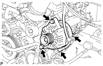
INSTALL GENERATOR
-
Install the generator bar with the 2 bolts.
- Torque:
- 43 N*m { 438 kgf*cm, 32 ft.*lbf }
-
Install the generator wire with the nut.
- Torque:
- 9.8 N*m { 100 kgf*cm, 87 in.*lbf }
-
Connect the generator connector.
-
-
INSTALL WATER INLET
-
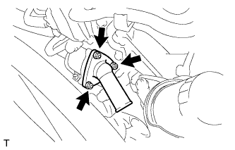
Install a new gasket to the water inlet housing with thermostat.
-
Install the water inlet housing with thermostat with the 3 nuts.
- Torque:
- 9.0 N*m { 92 kgf*cm, 80 in.*lbf }
-
-
INSTALL OIL DIPSTICK GUIDE
-
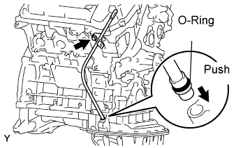
Install a new O-ring to the oil dipstick guide.
-
Apply a light coat of engine oil to the O-ring.
-
Push in the oil dipstick guide end into the guide hole of the oil pan.
-
Install the oil dipstick guide with the bolt.
- Torque:
- 9.0 N*m { 92 kgf*cm, 80 in.*lbf }
-
Install the oil dipstick gauge.
-
-
REMOVE ENGINE ASSEMBLY FROM STAND
-
INSTALL FLYWHEEL (for Manual Transmission)
-
Зафиксируйте коленчатый вал с помощью SST.
- SST
- 09213-54015 ( 91651-60855 )
- 09330-00021
-
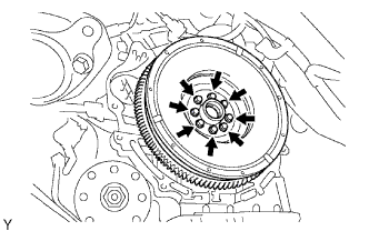
Временно закрепите маховик 8 новыми болтами.
-
Установите 8 болтов и затяните их равномерно в несколько этапов.
- Torque:
- 30 Н*м { 306 кгс*см, 22 фунт-сила-фута }
-
Отметьте верхнюю сторону болтов краской.
-
Затяните 8 болтов на 90° в той же последовательности.
-
Убедитесь, что метки повернуты на 90° относительно верхнего положения.
-
-
INSTALL DRIVE PLATE AND RING GEAR ASSEMBLY (for Automatic Transmission)
-
Зафиксируйте коленчатый вал с помощью SST.
- SST
- 09213-54015 ( 91651-60855 )
- 09330-00021
-
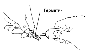
Нанесите герметик на последние 2-3 нитки резьбы каждого болта.
Герметик Герметик Toyota Genuine Adhesive 1324, Three Bond 1324 или аналогичный -
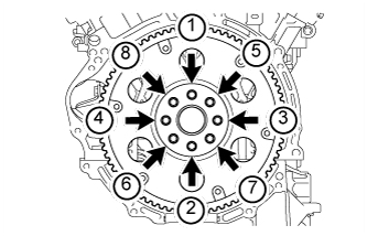
Установите переднюю распорную втулку, ведущий диск и заднюю распорную втулку на коленчатый вал.
-
В несколько этапов вверните и равномерно затяните 8 болтов в последовательности, показанной на рисунке.
- Torque:
- 83 Н*м { 846 кгс*см, 61 фунт-сила-футов }
-
-
CONNECT CABLE TO NEGATIVE BATTERY TERMINAL
Note
When disconnecting the cable, some systems need to be initialized after the cable is reconnected Click here.
-
ADD ENGINE OIL
-
Clean and install the oil drain plug with a new gasket.
- Torque:
- 40 N*m { 408 kgf*cm, 30 ft.*lbf }
-
Add fresh engine oil.
Standard capacity Item Capacity Drain and refill with oil filter change 5.5 liters (5.8 US qts, 4.8 Imp. qts) Drain and refill without oil filter change 5.2 liters (5.5 US qts, 4.6 Imp. qts) Dry fill 6.6 liters (7.0 US qts, 5.8 Imp. qts) Note
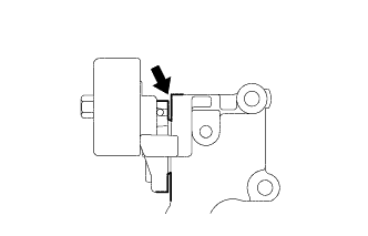
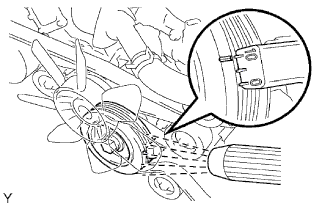
Do not allow engine oil to adhere to the moving parts of the belt tensioner, as this may cause malfunctions.
If engine oil is on the location indicated by the arrow, replace the belt tensioner.
-
Install the oil filler cap.
-
-
ADD ENGINE COOLANT
-
Tighten all the plugs and fill the radiator with TOYOTA Super Long Life Coolant (SLLC).
- Torque:
- 13 N*m { 130 kgf*cm, 9 ft.*lbf, for cylinder block drain cock plug }
Standard capacity Item Specified Condition A/T 9.8 liters (10.4 US qts, 8.6 Imp. qts) M/T 8.5 liters (9.0 US qts, 7.5 Imp. qts) Tech Tips
-
TOYOTA vehicles are filled with TOYOTA SLLC at the factory. In order to avoid damage to the engine cooling system and other technical problems, only use TOYOTA SLLC or similar high quality ethylene glycol based non-silicate, non-amine, non-nitrite, non-borate coolant with long-life hybrid organic acid technology (coolant with long-life hybrid organic and technology consists of a combination of low phosphates and organic acids).
-
Please contact your TOYOTA dealer for further details.
Note
Never use water as a substitute for engine coolant.
-
Press the inlet and outlet radiator hoses several times by hand, and then check the level of the coolant.
-
Install the radiator cap.
-
Bleed air from the cooling system.
-
Warm up the engine until the thermostat opens. While the thermostat is open, circulate the coolant for several minutes.
-
Maintain the engine speed at 2,000 to 2,500 rpm.
-
Press the inlet and outlet radiator hoses several times by hand to bleed air.
CAUTION:
When pressing the radiator hoses:
-
Wear protective gloves.
-
Be careful as the radiator hoses are hot.
-
Keep your hands away from the radiator fan.
-
-
-
Stop the engine and wait until the coolant cools down to ambient temperature.
CAUTION:
Do not remove the radiator cap while the engine and radiator are still hot. Pressurized, hot engine coolant and steam may be released and cause serious burns.
-
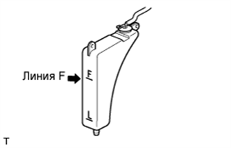
Check the coolant level in the radiator reservoir.
If the coolant level is low, add SLLC to the reservoir F line.
-
-
CHECK FOR ENGINE COOLANT LEAKS
CAUTION:
Do not remove the radiator cap while the engine and radiator are still hot. Pressurized, hot engine coolant and steam may be released and cause serious burns.
-
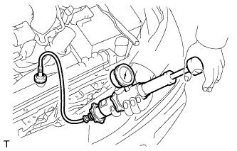
Fill the radiator with coolant and attach a radiator cap tester.
-
Warm up the engine.
-
Using the radiator cap tester, increase the pressure inside the radiator to 118 kPa (1.2 kgf/cm2, 17.1 psi), and check that the pressure does not drop.
If the pressure drops, check the hoses, radiator and water pump for leaks. If no external leaks are found, check the cylinder block and head.
-
-
CHECK FOR FUEL LEAKS
-
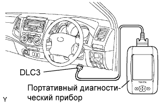
Connect the intelligent tester to the DLC3.
-
Turn the ignition switch ON.
Note
Do not start the engine.
-
Push the intelligent tester main switch ON.
-
Select Active Test and enter the following menus: Powertrain / Engine and ECT / Active Test / Control the Fuel Pump / Speed.
-
-
Check for fuel leaks.
-
Check that there are no fuel leaks after performing maintenance anywhere on the fuel system.
-
-
-
CHECK FOR ENGINE OIL LEAKS
-
После выполнения техобслуживания запустите двигатель и убедитесь в отсутствии утечек масла.
-
-
INSTALL V-BANK COVER
-
Install the V-bank cover with the 2 nuts.
- Torque:
- 7.5 N*m { 76 kgf*cm, 66 in.*lbf }
-
-
INSPECT IGNITION TIMING
-
When using intelligent tester:
Check the ignition timing.
-
Connect the intelligent tester to the DLC3.
Tech Tips
Please refer to the intelligent tester operator's manual for further details.
Ignition timing 7 to 24°BTDC @ idle (Transmission in neutral position) -
Disconnect the intelligent tester from the DLC3.
-
-
When not using intelligent tester.
Check the ignition timing.
-
Remove the air cleaner cap.
-
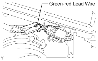
Connect the tester probe of a timing light to the green-red read wire of the ignition coil connector for the No.1 cylinder.
-
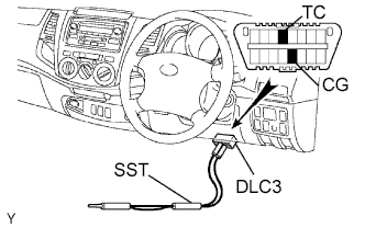
Using SST, connect terminals TC and CG of the DLC3.
- SST
- 09843-18040
-
Using the timing light, check the ignition timing.
Ignition timing 10 +- 2° BTDC @ idle (Transmission in neutral position) -
Remove the SST from the DLC3.
-
Check the ignition timing.
Ignition timing 7 to 24° BTDC @ idle (Transmission in neutral position) -
Disconnect the timing light from the engine.
-
Install the air cleaner cap.
-
-
-
INSPECT IDLE SPEED
-
When using intelligent tester:
Check the idle speed.
-
Connect the intelligent tester to the DLC3.
Tech Tips
Please refer to the intelligent tester operator's manual for further details.
-
Switch the air conditioning OFF.
-
Race the engine at 2,500 rpm for approximately 90 seconds.
-
Check the idle speed.
Idle speed 700 +- 50 rpm (Transmission in neutral position) If the idle speed is not as specified, check the air intake system
-
Disconnect the intelligent tester from the DLC3.
-
-
When not using intelligent tester:
Check the idle speed.
-
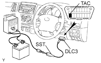
Using SST, connect tachometer probe to terminal TAC of the DLC3.
- SST
- 09843-18030
-
Switch the air conditioning OFF.
-
Race the engine speed at 2,500 rpm for approximately 90 seconds.
-
Check the idle speed.
Idle speed 700 +- 50 rpm (Transmission in neutral position) If the idle speed is not as specified, check the air intake system.
-
Disconnect the tachometer from the DLC3.
-
-
-
INSPECT CO/HC
Tech Tips
This check is for determining whether or not the idle CO/HC complies with regulations.
-
Start the engine.
-
Keep the engine speed at 2,500 rpm for approximately 180 seconds.
-
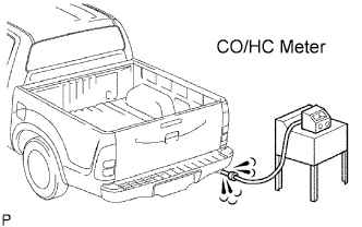
Insert CO/HC meter testing probe at least 40 cm (1.3 ft.) into the tailpipe during idling.
-
Immediately check CO/HC concentration at idle and/or 2,500 rpm.
Tech Tips
When performing the 2 mode (2,500 rpm and idle) test, follow the measurement order prescribed by the applicable local regulations.
If the CO/HC concentration does not comply with regulations, troubleshoot in the order given below.
-
Check the A/F sensor operation and heated oxygen sensor operation.
-
See the table below for possible causes, then inspect and correct the applicable causes if necessary.
CO HC Symptom Causes Normal High Rough idle 1. Faulty ignitions:
-
Incorrect timing
-
Fouled, shorted or improperly gapped plugs
2. Incorrect valve clearance
3. Leaky intake and exhaust valves
4. Leaky cylinder
Low High Rough idle
(Fluctuating HC reading)
1. Vacuum leaks:
-
PCV hose
-
Intake manifold
-
Throttle body
2. Lean mixture causing misfire.
High High Rough idle
(Black smoke from exhaust)
1. Restricted air filter
2. Faulty SFI system:
-
Faulty pressure regulator
-
Defective ECT sensor
-
Faulty ECM
-
Faulty injector
-
Faulty throttle position sensor
-
Faulty MAF sensor
-
-
-