SFI SYSTEM, Diagnostic DTC:P0230
| DTC Code | DTC Name |
|---|---|
| P0230 | Fuel Pump Primary Circuit |
DESCRIPTION
When a malfunction in the fuel pump control circuit (low pressure side) is detected, DTC P0230 is stored.
The fuel pump control circuit (low pressure side) consists of the ECM, fuel pump assembly and fuel pump control ECU assembly (which operates the fuel pump assembly). Based on the engine output, the ECM determines the fuel pump speed. The speed is then converted to a duty signal and sent to the fuel pump control ECU assembly. Based on the signal sent from the ECM, the fuel pump control ECU assembly adjusts the fuel pump assembly operation speed among 3 settings. The fuel pump control ECU assembly also has a self-diagnosis function. Based on the fuel pump control circuit (low pressure side) condition, the fuel pump control ECU assembly outputs a diagnostic signal to the ECM, and the ECM determines if there is a malfunction in the fuel pump control circuit (low pressure side).
| DTC No. | DTC Detection Condition | Trouble Area |
|---|---|---|
| P0230 | Open or short in fuel pump circuit for 2.5 seconds or more. (1 trip detection logic) |
|
MONITOR DESCRIPTION
To monitor the fuel pump control circuit (low pressure side), the ECM checks the fuel pump control signal (FPC) and diagnostic signal (DI). The FPC voltage varies between approximately 0 V and approximately 12 V (duty signal). Based on the condition of the fuel pump control ECU assembly malfunction, the DI voltage varies between approximately 0 V and approximately 12 V. The ECM then compares the variation of the FPC voltage and DI voltage, and determines if the fuel pump control circuit (low pressure side) is malfunctioning. When the ECM determines that the fuel pump control circuit (low pressure side) is malfunctioning, a DTC is stored immediately.
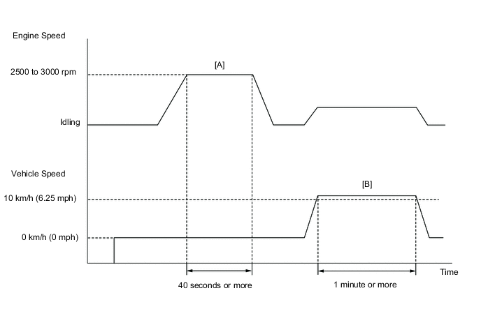
CONFIRMATION DRIVING PATTERN
-
-
Connect the GTS to the DLC3.
-
Turn the ignition switch to ON and turn the GTS on.
-
Clear DTCs (even if no DTCs are stored, perform the clear DTC operation) Click here.
-
Turn the ignition switch off and wait for at least 30 seconds.
-
Turn the ignition switch to ON and turn the GTS on.
-
Start the engine and warm it up until the engine coolant temperature reaches 75°C (167°F) or higher.
-
With the vehicle stationary, depress the accelerator pedal and maintain an engine speed of between 2500 and 3000 rpm for 40 seconds or more [A].
-
Drive the vehicle at 10 km/h (6.25 mph) or more for 1 minute or more [B].
CAUTION:
When performing the confirmation driving pattern, obey all speed limits and traffic laws.
-
Enter the following menus: Powertrain / Engine / Trouble Codes.
-
Read pending DTCs.
Tech Tips
-
If a pending DTC is output, the system is malfunctioning.
-
If a pending DTC is not output, perform the following procedure.
-
-
Enter the following menus: Powertrain / Engine / Utility / All Readiness.
-
Input the DTC: P0230.
-
Check the DTC judgment result.
GTS Display Description NORMAL
-
DTC judgment completed
-
System normal
ABNORMAL
-
DTC judgment completed
-
System abnormal
INCOMPLETE
-
DTC judgment not completed
-
Perform driving pattern after confirming DTC enabling conditions
N/A
-
Unable to perform DTC judgment
-
Number of DTCs which do not fulfill DTC preconditions has reached ECU memory limit
Tech Tips
-
If the judgment result shows NORMAL, the system is normal.
-
If the judgment result shows ABNORMAL, the system has a malfunction.
-
-
If the test result is INCOMPLETE or N/A and no DTC is output, perform a universal trip and check for permanent DTCs Click here.
Tech Tips
-
If a permanent DTC is output, the system is malfunctioning.
-
If no permanent DTC is output, the system is normal.
-
WIRING DIAGRAM
Refer to Fuel Pump Control Circuit Click here.
CAUTION / NOTICE / HINT
This troubleshooting procedure is based on the premise that the engine is started. If the engine is not started, proceed to Problem Symptoms Table Click here.
Note
Inspect the fuses for circuits related to this system before performing the following inspection procedure.
PROCEDURE
-
INSPECT TERMINAL VOLTAGE (+B OF FUEL PUMP CONTROL ECU ASSEMBLY)
-
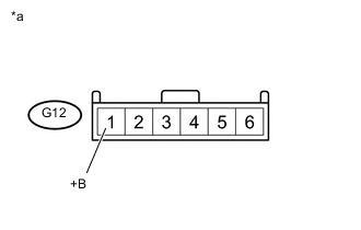
Text in Illustration *a Front view of wire harness connector
(to Fuel Pump Control ECU Assembly)
Disconnect the fuel pump control ECU assembly connector.
-
Measure the voltage according to the value(s) in the table below.
Standard Voltage Tester Connection Switch Condition Specified Condition G12-1 (+B) - Body ground Ignition switch ON 11 to 14 V
NG 
INSPECT RELAY (C/OPEN) Click here
OK 
-
-
CHECK HARNESS AND CONNECTOR (FUEL PUMP CONTROL ECU ASSEMBLY - BODY GROUND)
-
Disconnect the fuel pump control ECU assembly connector.
-
Measure the resistance according to the value(s) in the table below.
Standard Resistance (Check for open) Tester Connection Condition Specified Condition G12-4 (E) - Body ground Always Below 1 Ω
NG 
REPAIR OR REPLACE HARNESS OR CONNECTOR
OK
-
-
CHECK HARNESS AND CONNECTOR (ECM - FUEL PUMP CONTROL ECU ASSEMBLY)
-
Disconnect the ECM connector.
-
Disconnect the fuel pump control ECU assembly connector.
-
Measure the resistance according to the value(s) in the table below.
Standard Resistance (Check for open) Tester Connection Condition Specified Condition A35-10 (DI) - G12-3 (DI) Always Below 1 Ω A35-19 (FPC) - G12-2 (FPC) Always Below 1 Ω Standard Resistance (Check for short) Tester Connection Condition Specified Condition A35-10 (DI) or G12-3 (DI) - Body ground Always 10 kΩ or higher A35-19 (FPC) or G12-2 (FPC) - Body ground Always 10 kΩ or higher
NG
REPAIR OR REPLACE HARNESS OR CONNECTOR
OK
-
-
INSPECT FUEL PUMP ASSEMBLY
-
Inspect the fuel pump assembly Click here.
NG
CHECK HARNESS AND CONNECTOR (FUEL PUMP CONTROL ECU ASSEMBLY - FUEL PUMP ASSEMBLY) Click here
OK
-
-
REPLACE FUEL PUMP CONTROL ECU ASSEMBLY
-
Replace the fuel pump control ECU assembly Click here.
NEXT
-
-
CONFIRM WHETHER DTC OUTPUT RECURS
-
Connect the GTS to the DLC3.
-
Turn the ignition switch to ON and turn the GTS on.
-
Clear the DTCs Click here.
-
Crank the engine for 15 seconds.
-
Idle the engine for 1 minute.
-
Enter the following menus: Powertrain / Engine / DTC.
-
Read the DTCs.
Result Result Proceed to No DTC output A DTC P0230 output B
A
END
B
REPLACE ECM Click here
-
-
CHECK HARNESS AND CONNECTOR (FUEL PUMP CONTROL ECU ASSEMBLY - FUEL PUMP ASSEMBLY)
-
Disconnect the fuel pump control ECU assembly connector.
-
Disconnect the fuel pump assembly connectors.
-
Measure the resistance according to the value(s) in the table below.
Standard Resistance (Check for open) Tester Connection Condition Specified Condition G12-5 (FP-) - G7-4 (FP-) Always Below 1 Ω G12-6 (FP+) - G7-3 (FP+) Always Below 1 Ω Standard Resistance (Check for short) Tester Connection Condition Specified Condition G12-5 (FP-) or G7-4 (FP-) - Body ground Always 10 kΩ or higher G12-6 (FP+) or G7-3 (FP+) - Body ground Always 10 kΩ or higher
OK
REPLACE FUEL PUMP ASSEMBLY Click here
NG
REPAIR OR REPLACE HARNESS OR CONNECTOR
-
-
INSPECT RELAY (C/OPEN)
-
Inspect the C/OPEN relay Click here.
NG
REPLACE RELAY (C/OPEN)
OK
-
-
INSPECT RELAY (C/OPEN RELAY OPERATION)
-
Check the relay operation sound when the ignition switch is turned to ON.
Result Item Condition Standard C/OPEN RELAY Ignition switch OFF → Ignition switch ON Operation sound is heard.
NG
REPAIR OR REPLACE HARNESS OR CONNECTOR
OK
-
-
CHECK HARNESS AND CONNECTOR (C/OPEN RELAY - FUEL PUMP CONTROL ECU ASSEMBLY)
-
Remove the C/OPEN relay from the engine room relay block assembly.
-
Disconnect the fuel pump control ECU assembly connector.
-
Measure the resistance according to the value(s) in the table below.
Standard Resistance (Check for open) Tester Connection Condition Specified Condition C/OPEN relay terminal 3 - G12-1 Always Below 1 Ω C/OPEN relay terminal 1 - Body ground Always Below 1 Ω Standard Resistance (Check for short) Tester Connection Condition Specified Condition C/OPEN relay terminal 3 or G12-1 - Body ground Always 10 kΩ or higher
OK
GO TO ECM POWER SOURCE CIRCUIT Click here
NG
REPAIR OR REPLACE HARNESS OR CONNECTOR
-