NAVIGATION SYSTEM(for Sedan), Diagnostic DTC:B158F
| DTC Code | DTC Name |
|---|---|
| B158F | AV Signal Stoppage (Low Battery Voltage) |
DESCRIPTION
This DTC is stored when a video or audio signal is interrupted due to battery voltage input to the radio and display receiver assembly dropping temporarily.
DTC No. |
Detection Item |
DTC Detection Condition |
Trouble Area |
|---|---|---|---|
B158F |
AV Signal Stoppage (Low Battery Voltage) |
A video or audio signal is interrupted when the battery voltage drops |
|
*1: w/ Stop and Start System
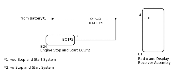
WIRING DIAGRAM
CAUTION / NOTICE / HINT
Inspect the fuses for circuits related to this system before performing the following procedure.
PROCEDURE
CHECK VEHICLE SIGNAL (OPERATION CHECK)
-
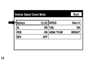
Enter the "Vehicle Signal Check Mode" screen. Refer to Check Vehicle Signal in Operation Check.
Measure the battery voltage.
Standard Voltage
11 to 14 V (w/o Stop and Start System)
9.5 to 14 V (w/ Stop and Start System)
Tip:This display is updated once per second.
Result
Proceed to
OK
NG
NG CONFIRM MODELClick here
-
CHECK DTC
Clear the DTCs.
Body Electrical > Navigation System > Clear DTCs
Recheck for DTCs and check that no DTCs are output.
Body Electrical > Navigation System > Trouble Codes
OK
No DTCs are output.
Result
Proceed to
OK
NG
OK END
CONFIRM MODEL
Choose the model to be inspected.
Result
Result
Proceed to
w/o Stop and Start System
A
w/ Stop and Start System
B
B CHECK HARNESS AND CONNECTOR (RADIO AND DISPLAY RECEIVER ASSEMBLY - ENGINE STOP AND START ECU)Click here
CHECK HARNESS AND CONNECTOR (RADIO AND DISPLAY RECEIVER ASSEMBLY POWER SOURCE)
Disconnect the E1 radio and display receiver assembly connector.
Measure the voltage according to the value(s) in the table below.
Standard Voltage
Tester Connection
Condition
Specified Condition
E1-4 (+B1) - Body ground
Always
11 to 14 V
Result
Proceed to
OK
NG
NG REPAIR OR REPLACE HARNESS OR CONNECTOR
CHECK HARNESS AND CONNECTOR (RADIO AND DISPLAY RECEIVER ASSEMBLY - ENGINE STOP AND START ECU)
Disconnect the E1 radio and display receiver assembly connector.
Disconnect the E24 engine stop and start ECU connector.
Measure the resistance according to the value(s) in the table below.
Standard Resistance
Tester Connection
Condition
Specified Condition
E1-4 (+B1) - E24-2 (BO1)
Always
Below 1 Ω
E1-4 (+B1) - Body ground
Always
10 kΩ or higher
Result
Proceed to
OK
NG
NG REPAIR OR REPLACE HARNESS OR CONNECTOR
CHECK HARNESS AND CONNECTOR (RADIO AND DISPLAY RECEIVER ASSEMBLY POWER SOURCE)
Disconnect the E1 radio and display receiver assembly connector.
Reconnect the E24 engine stop and start ECU connector.
Measure the voltage according to the value(s) in the table below.
Standard Voltage
Tester Connection
Condition
Specified Condition
E1-4 (+B1) - Body ground
Always
9.5 to 14 V
Result
Proceed to
OK
NG