EXHAUST PIPE INSTALLATION
PROCEDURE
-
INSTALL FRONT EXHAUST PIPE ASSEMBLY (w/ Exhaust Heat Recirculation System)
Note
When installing the water hose, ensure that the exhaust heat recirculation system is filled with coolant. Otherwise, the engine water pump assembly may be damaged.
-
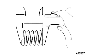
Using a vernier caliper, measure the free length of the compression springs.
Minimum 41.5 mm (1.64 in.) Tech Tips
If the free length is less than the minimum, replace the compression spring.
-
Fully insert a new gasket to the exhaust manifold.
-
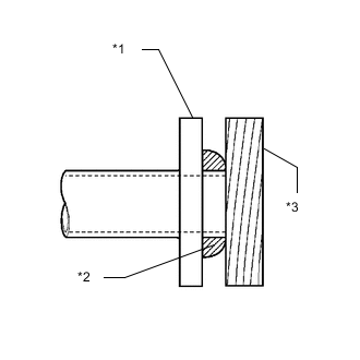
Text in Illustration *1 Exhaust Manifold *2 Gasket *3 Wooden Block Using a plastic hammer and wooden block, tap in the new gasket until its surface is flush with the exhaust manifold.
Note
-
Be careful with the installation direction of the gasket.
-
Do not reuse the gasket.
-
Do not damage the gasket.
-
Do not push in the gasket by using the exhaust pipe when connecting it.
-
-
Connect the front exhaust pipe assembly to the 3 exhaust pipe supports.
-
Install the front exhaust pipe assembly with the 2 bolts and 2 compression springs.
- Torque:
- 43 N*m { 438 kgf*cm, 32 ft.*lbf }
-
Connect the 2 heater water hoses.
-
-
INSTALL FRONT EXHAUST PIPE ASSEMBLY (w/o Exhaust Heat Recirculation System)
-
Using a vernier caliper, measure the free length of the compression springs.
Minimum 41.5 mm (1.64 in.) Tech Tips
If the free length is less than the minimum, replace the compression spring.
-
Fully insert a new gasket to the exhaust manifold.
-
Text in Illustration *1 Exhaust Manifold *2 Gasket *3 Wooden Block Using a plastic hammer and wooden block, tap in the new gasket until its surface is flush with the exhaust manifold.
Note
-
Be careful with the installation direction of the gasket.
-
Do not reuse the gasket.
-
Do not damage the gasket.
-
Do not push in the gasket by using the exhaust pipe when connecting it.
-
-
Connect the front exhaust pipe assembly to the 3 exhaust pipe supports.
-
Install the front exhaust pipe assembly with the 2 bolts and 2 compression springs.
- Torque:
- 43 N*m { 438 kgf*cm, 32 ft.*lbf }
-
-
INSTALL HEATED OXYGEN SENSOR
-
INSTALL FRONT CENTER FLOOR BRACE
-
Install the front center floor brace with the 4 bolts.
- Torque:
- 51 N*m { 520 kgf*cm, 38 ft.*lbf }
-
-
INSTALL FRONT NO. 3 ENGINE UNDER COVER
-
INSTALL TAIL EXHAUST PIPE ASSEMBLY
-
Using a vernier caliper, measure the free length of the compression springs.
Minimum 38.5 mm (1.52 in.) Tech Tips
If the free length is less than the minimum, replace the compression spring.
-
Fully insert a new gasket to the front exhaust pipe assembly.
-
Text in Illustration *1 Front Exhaust Pipe Assembly *2 Gasket *3 Wooden Block Using a plastic hammer and wooden block, tap in the new gasket until its surface is flush with the front exhaust pipe assembly.
Note
-
Be careful with the installation direction of the gasket.
-
Do not reuse the gasket.
-
Do not damage the gasket.
-
Do not push in the gasket by using the exhaust pipe when connecting it.
-
-
Connect the tail exhaust pipe assembly to the 2 exhaust pipe supports.
-
Install the tail exhaust pipe assembly with the 2 bolts and 2 compression springs.
- Torque:
- 43 N*m { 438 kgf*cm, 32 ft.*lbf }
-
-
ADD COOLANT (for Engine with Exhaust Heat Recirculation System)
-
INSPECT FOR COOLANT LEAK (for Engine with Exhaust Heat Recirculation System)
-
INSPECT FOR EXHAUST GAS LEAK