EMISSION CONTROL SYSTEM(w/ Canister Pump Module)
-
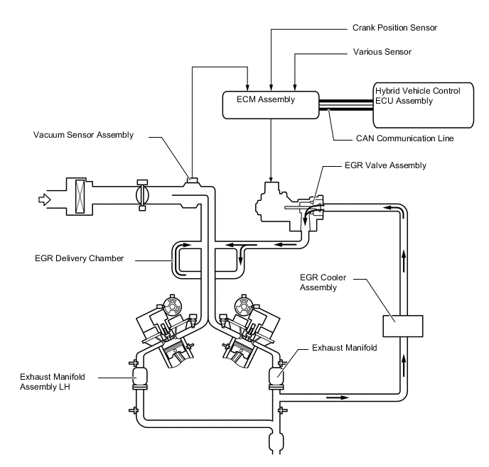
FUNCTION OF MAIN COMPONENTS
Component Function Vacuum Sensor Assembly Detects the pressure in the intake air surge tank assembly and sends signals to the ECM assembly. EGR Valve Assembly Opens and closes based on signals from the ECM assembly and controls the flow rate of the exhaust gas in the EGR bypass. EGR Cooler Assembly The EGR cooler assembly cools the exhaust gas to improve EGR efficiency. Intake Manifold EGR Delivery Chamber Distributes recirculated exhaust gasses equally to each cylinder. Hybrid Vehicle Control ECU Assembly Sends signals such as the accelerator pedal position sensor signal to the ECM assembly. ECM Assembly Based on the signals received from the sensors, the ECM assembly determines the EGR volume in accordance with engine operating conditions. -
SYSTEM CONTROL
-
Cooled Exhaust Gas Recirculation (EGR) control regulates the EGR valve assembly according to driving conditions for fuel economy.
-
This control uses the ECM assembly, crank position sensor, vacuum sensor assembly, EGR valve assembly and various sensors.
-
This system recirculates some of the exhaust gas to the combustion chambers, helping enhance fuel efficiency by reducing the following 3 losses:
-
Recirculation of exhaust gas allows the pressure in the intake manifold to be made closer to atmospheric pressure, this helps to reduce pumping losses.
-
Mixing intake air and exhaust gas allows oxygen concentration in the combustion chamber to be reduced, moderating combustion and thereby reducing combustion temperature. This reduces cooling losses.
-
As the combustion temperature is lowered, it becomes harder for the mixture to preignite. This allows more ignition timing advance to be used. As a result of using more ignition timing advance, the pressure in the cylinder at bottom dead center after expansion of the burning mixture will decrease, reducing exhaust losses.
-
-