WIPER AND WASHER SYSTEM, Diagnostic DTC:B1245
| DTC Code | DTC Name |
|---|---|
| B1245 | Lost Communication with Wiper ECU LIN |
DESCRIPTION
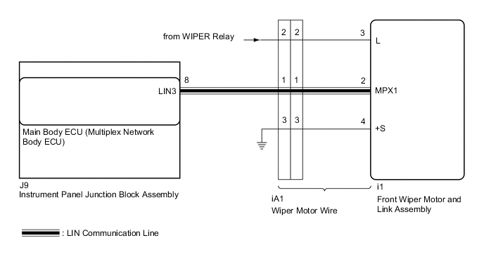
The main body ECU (multiplex network body ECU) and front wiper motor and link assembly communicate via LIN communication. The main body ECU (multiplex network body ECU) stores this DTC if communication becomes abnormal.
| DTC No. | Detection Item | DTC Detection Condition | Trouble Area | Memory | DTC Output from |
|---|---|---|---|---|---|
| B1245 | Lost Communication with Wiper ECU LIN | When the battery voltage is 9.5 V or more, a communication malfunction between the main body ECU (multiplex network body ECU) and front wiper motor and link assembly is detected for 10 seconds or more. |
|
○ | Main body ECU (multiplex network body ECU) |
WIRING DIAGRAM
PROCEDURE
-
CLEAR DTC
-
Clear the DTCs.
Body Electrical > Main Body > Clear DTCsResult Proceed to NEXT
NEXT 
-
-
CHECK FOR DTC
-
Turn the engine switch on (IG).
-
Check for DTCs.
Body Electrical > Main Body > Trouble CodesResult Result Proceed to DTC B1245 is not output. A DTC B1245 is output. B
A 
USE SIMULATION METHOD TO CHECK Click here
B
-
-
CHECK HARNESS AND CONNECTOR (MAIN BODY ECU (MULTIPLEX NETWORK BODY ECU) - FRONT WIPER MOTOR AND LINK ASSEMBLY)
-
Disconnect the J9 main body ECU (multiplex network body ECU) connector.
-
Disconnect the i1 front wiper motor and link assembly connector.
-
Measure the resistance according to the value(s) in the table below.
Standard Resistance Tester Connection Condition Specified Condition J9-8 (LIN3) - i1-2 (MPX1) Always Below 1 Ω J9-8 (LIN3) or i1-2 (MPX1) - Body ground Always 10 kΩ or higher Result Proceed to OK NG
NG 
CHECK WIPER MOTOR WIRE Click here
OK
-
-
CHECK HARNESS AND CONNECTOR (FRONT WIPER MOTOR AND LINK ASSEMBLY - POWER SOURCE)
-
Measure the voltage according to the value(s) in the table below.
Standard Voltage Tester Connection Condition Specified Condition i1-3 (L) - Body ground Engine switch off Below 1 V Engine switch on (IG) 11 to 14 V Result Proceed to OK NG
NG
CHECK WIPER MOTOR WIRE Click here
OK
-
-
CHECK HARNESS AND CONNECTOR (FRONT WIPER MOTOR AND LINK ASSEMBLY - BODY GROUND)
-
Measure the resistance according to the value(s) in the table below.
Standard Resistance Tester Connection Condition Specified Condition i1-4 (+S) - Body ground Always Below 1 Ω Result Proceed to OK NG
NG
CHECK WIPER MOTOR WIRE Click here
OK
-
-
REPLACE FRONT WIPER MOTOR AND LINK ASSEMBLY
-
Replace the front wiper motor and link assembly with a new or known good one.
-
Turn the engine switch on (IG).
-
Check for DTCs.
Body Electrical > Main Body > Trouble CodesResult Result Proceed to DTC B1245 is not output. A DTC B1245 is output. B
A
END
B
REPLACE MAIN BODY ECU (MULTIPLEX NETWORK BODY ECU) Click here
-
-
CHECK WIPER MOTOR WIRE
-
Remove the wiper motor wire.
-
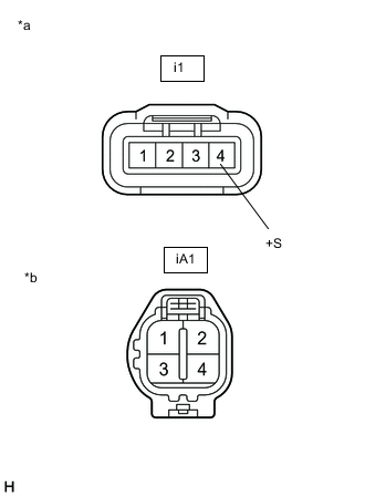
*a Front view of wire harness connector
(to Front Wiper Motor and Link Assembly)
*b Front view of wire harness connector
(to Wire Harness)
Measure the resistance according to the value(s) in the table below.
Standard Resistance Tester Connection Condition Specified Condition i1-4 (+S) - iA1-3 Always Below 1 Ω Result Proceed to OK NG
OK
REPAIR OR REPLACE HARNESS OR CONNECTOR
NG
REPLACE WIPER MOTOR WIRE Click here
-
-
CHECK WIPER MOTOR WIRE
-
Remove the wiper motor wire.
-
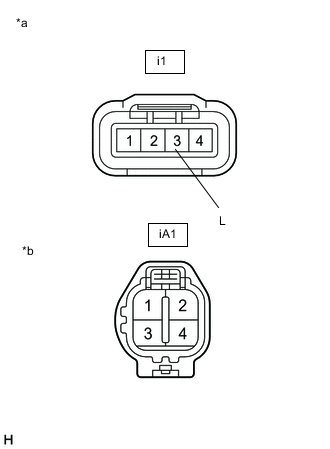
*a Front view of wire harness connector
(to Front Wiper Motor and Link Assembly)
*b Front view of wire harness connector
(to Wire Harness)
Measure the resistance according to the value(s) in the table below.
Standard Resistance Tester Connection Condition Specified Condition i1-3 (L) - iA1-2 Always Below 1 Ω Result Proceed to OK NG
OK
REPAIR OR REPLACE HARNESS OR CONNECTOR
NG
REPLACE WIPER MOTOR WIRE Click here
-
-
CHECK WIPER MOTOR WIRE
-
Remove the wiper motor wire.
-
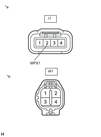
*a Front view of wire harness connector
(to Front Wiper Motor and Link Assembly)
*b Front view of wire harness connector
(to Wire Harness)
Measure the resistance according to the value(s) in the table below.
Standard Resistance Tester Connection Condition Specified Condition i1-2 (MPX1) - iA1-1 Always Below 1 Ω Result Proceed to OK NG
OK
REPAIR OR REPLACE HARNESS OR CONNECTOR
NG
REPLACE WIPER MOTOR WIRE Click here
-