LIGHTING SYSTEM(w/o Automatic Headlight Beam Level Control System) High Beam Headlight Circuit
DESCRIPTION
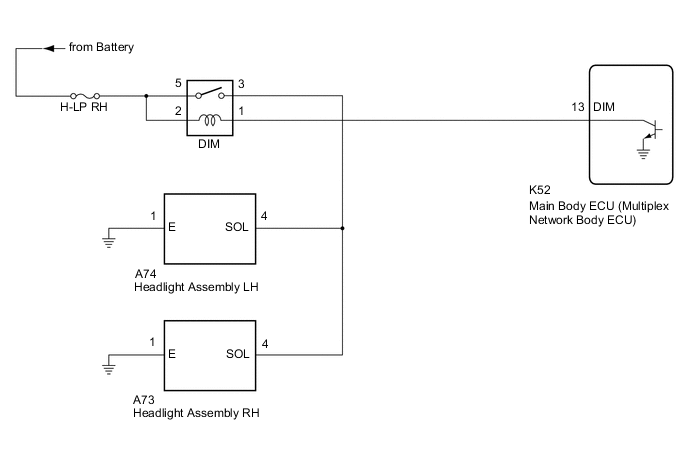
The main body ECU (multiplex network body ECU) controls the high beam headlights.
WIRING DIAGRAM
CAUTION / NOTICE / HINT
Note
-
Inspect the fuses for circuits related to this system before performing the following procedure.
-
Check the operation of the low beam headlights. If the low beam headlights do not operate normally, refer to Problem Symptoms Table.
-
Before replacing the main body ECU (multiplex network body ECU), refer to Service Bulletin.*
-
*: w/ Smart Entry and Start System
PROCEDURE
-
PERFORM ACTIVE TEST USING GTS
-
Connect the GTS to the DLC3.
-
Turn the ignition switch to ON.
-
Turn the GTS on.
-
Enter the following menus: Body Electrical / Main Body / Active Test.
-
Perform the Active Test according to the display on the GTS.
Body Electrical > Main Body > Active TestTester Display Measurement Item Control Range Diagnostic Note Head Light Hi High beam headlights OFF or ON -
Body Electrical > Main Body > Active TestTester Display Head Light Hi OK High beam headlights illuminate. Result Proceed to OK NG
OK 
PROCEED TO NEXT SUSPECTED AREA SHOWN IN PROBLEM SYMPTOMS TABLE Click here
NG 
-
-
INSPECT DIM RELAY
-
Inspect the DIM relay.
Result Proceed to OK NG
NG
REPLACE DIM RELAY
OK
-
-
CHECK HARNESS AND CONNECTOR (POWER SOURCE - DIM RELAY)
-
Measure the voltage according to the value(s) in the table below.
Standard Voltage Tester Connection Condition Specified Condition 2 (DIM relay) - Body ground Always 11 to 14 V 5 (DIM relay) - Body ground Always 11 to 14 V Result Proceed to OK NG
NG
REPAIR OR REPLACE HARNESS OR CONNECTOR
OK
-
-
CHECK HARNESS AND CONNECTOR (DIM RELAY - MAIN BODY ECU (MULTIPLEX NETWORK BODY ECU))
-
Disconnect the K52 main body ECU (multiplex network body ECU) connector.
-
Measure the resistance according to the value(s) in the table below.
Standard Resistance Tester Connection Condition Specified Condition 1 (DIM relay) - K52-13 (DIM) Always Below 1 Ω 1 (DIM relay) or K52-13 (DIM) - Body ground Always 10 kΩ or higher Result Proceed to OK NG
OK
REPLACE MAIN BODY ECU (MULTIPLEX NETWORK BODY ECU) Click here
NG
REPAIR OR REPLACE HARNESS OR CONNECTOR
-