TIRE PRESSURE WARNING SYSTEM, Diagnostic DTC:C2121/21, C2122/22, C2123/23, C2124/24, C2125/25, C2181/81, C2182/82, C2183/83, C2184/84, C2185/85
| DTC Code | DTC Name |
|---|---|
| C2121/21 | No Signal from Transmitter ID1 |
| C2122/22 | No Signal from Transmitter ID2 |
| C2123/23 | No Signal from Transmitter ID3 |
| C2124/24 | No Signal from Transmitter ID4 |
| C2125/25 | No Signal from Transmitter ID5 |
| C2181/81 | Transmitter ID1 not Received (Test Mode DTC) |
| C2182/82 | Transmitter ID2 not Received (Test Mode DTC) |
| C2183/83 | Transmitter ID3 not Received (Test Mode DTC) |
| C2184/84 | Transmitter ID4 not Received (Test Mode DTC) |
| C2185/85 | Transmitter ID5 not Received (Test Mode DTC) |
DESCRIPTION
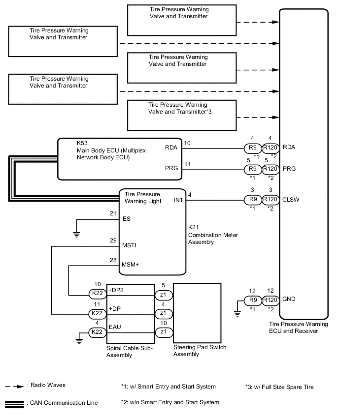
The tire pressure warning valve and transmitters that are installed in the tire and wheel assemblies measure the tire pressure of each wheel. The measured values are transmitted to the tire pressure warning ECU and receiver in the vehicle as radio waves. The ECU compares the measured tire pressure values with the tire pressure threshold. When the measured tire pressure value is less than this threshold, the warning light in the combination meter assembly illuminates.
The tire pressure warning valve and transmitters constantly send radio waves to the tire pressure warning ECU and receiver.
Under the conditions below, the tire pressure warning ECU and receiver is unable to receive the signals from the tire pressure warning valve and transmitters, and a DTC is stored.
-
Facilities or devices that use similar radio frequencies are located in the vicinity of the vehicle.
-
Devices using similar radio frequencies are used in the vehicle.
-
The ID of a tire pressure warning valve and transmitter is mistyped during registration.
-
A tire, wheel and/or transmitter from a different vehicle is installed.
Tech Tips
When no transmitter ID is received from a tire pressure warning valve and transmitter for 10 minutes or more while the vehicle speed is more than 40 km/h (25 mph), or no transmitter ID is received from all of the tire pressure warning valve and transmitters for 10 minutes or more, DTCs from C2121/21 to C2124/24 (C2125/25: w/ Full Size Spare Tire) are stored.
DTCs C2121/21 to C2124/24 (C2125/25: w/ Full Size Spare Tire) can only be cleared by using the GTS. DTCs C2181/81 to C2184/84 (C2185/85: w/ Full Size Spare Tire) can be cleared when the tire pressure warning valve and transmitter sends a forced transmission signal or test mode ends. DTCs C2181/81 to C2184/84 (C2185/85: w/ Full Size Spare Tire) are output only in test mode.
| DTC No. | Detection Item | DTC Detection Condition | Trouble Area | Note |
|---|---|---|---|---|
| C2121/21 | No Signal from Transmitter ID1 | Either of the following conditions (a) or (b) is met: (a) When all conditions below are met:
(b) When both conditions below are met:
|
|
- |
| C2122/22 | No Signal from Transmitter ID2 | Either of the following conditions (a) or (b) is met: (a) When all conditions below are met:
(b) When both conditions below are met:
|
|
- |
| C2123/23 | No Signal from Transmitter ID3 | Either of the following conditions (a) or (b) is met: (a) When all conditions below are met:
(b) When both conditions below are met:
|
|
- |
| C2124/24 | No Signal from Transmitter ID4 | Either of the following conditions (a) or (b) is met: (a) When all conditions below are met:
(b) When both conditions below are met:
|
|
- |
| C2125/25 | No Signal from Transmitter ID5 | Either of the following conditions (a) or (b) is met: (a) When all conditions below are met:
(b) When both conditions below are met:
|
|
w/ Full Size Spare Tire |
| C2181/81 | Transmitter ID1 not Received (Test Mode DTC) | Test mode procedure is performed. |
|
- |
| C2182/82 | Transmitter ID2 not Received (Test Mode DTC) | Test mode procedure is performed. |
|
- |
| C2183/83 | Transmitter ID3 not Received (Test Mode DTC) | Test mode procedure is performed. |
|
- |
| C2184/84 | Transmitter ID4 not Received (Test Mode DTC) | Test mode procedure is performed. |
|
- |
| C2185/85 | Transmitter ID5 not Received (Test Mode DTC) | Test mode procedure is performed. |
|
w/ Full Size Spare Tire |
Note
-
w/ ID Switching Function:
Even when the 2nd tire set is selected, "(Main)" is displayed on the GTS.
-
When DTCs C2121/21 to C2124/24 (C2125/25: w/ Full Size Spare Tire) are set, DTC C2179/79 may be set simultaneously. In such cases, troubleshoot DTCs C2121/21 to C2124/24 (C2125/25: w/ Full Size Spare Tire) first, then troubleshoot DTC C2179/79.
-
If the GTS is used to display the Data List for 10 minutes or more, the tire pressure warning ECU stores DTCs C2121/21 to C2124/24 (C2125/25: w/ Full Size Spare Tire). If these DTCs are stored, clear the DTCs using the GTS.
-
w/o Full Size Spare Tire:
If any DTC from C2121/21 to C2124/24 is output, clear the DTCs or drive the vehicle at 40 km/h (25 mph) for 1 minute or more after repairing the malfunctions.
-
w/ Full Size Spare Tire:
If any DTC from C2121/21 to C2125/25 is output, clear the DTCs after repairing the malfunctions.
Tech Tips
It is necessary to perform the following procedure to identify the tire pressure warning valve and transmitter that is malfunctioning because it cannot be identified by the output DTC.
WIRING DIAGRAM
CAUTION / NOTICE / HINT
Note
-
When replacing the tire pressure warning ECU and receiver or tire pressure warning valve and transmitter, read the transmitter IDs and number of the transmitters (4 or 5) stored in the old ECU using the GTS and write them down before removal.
-
It is necessary to perform initialization after registration Click here of the transmitter IDs into the tire pressure warning ECU and receiver if the ECU and/or one of the valve and transmitters has been replaced.
PROCEDURE
-
CHECK FREQUENCY RECEIVING CONDITION
-
Check that the following conditions are not met:
-
Facilities or devices that use similar radio frequencies are located in the vicinity of the vehicle.
Tech Tips
If the vehicle is located in an area such as the one described above, the tire pressure warning light may illuminate after blinking for 1 minute due to interfering radio frequencies.
-
Devices using similar radio frequencies are used in the vehicle.
Tech Tips
Radio transmissions may be interrupted due to the surroundings or devices installed by the user.
Result Result Proceed to There is no device or facility that uses electrical waves of approximately the same frequency in the vicinity of the vehicle or inside the vehicle. A There is a device or facility that uses electrical waves of approximately the same frequency in the vicinity of the vehicle or inside the vehicle. B -
B 
CLEAR DTC Click here
A 
-
-
CONFIRM OUTPUT DTC
-
Check the stored DTC.
Result Result Proceed to Any DTCs from C2121/21 to C2124/24 (C2125/25: w/ Full Size Spare Tire) are output (C2181/81 to C2184/84 (C2185/85: w/ Full Size Spare Tire) when in Test Mode) A All DTCs from C2121/21 to C2124/24 (C2125/25: w/ Full Size Spare Tire) are output (C2181/81 to C2184/84 (C2185/85: w/ Full Size Spare Tire) when in Test Mode) B
B
TEST MODE INSPECTION (C2181/81 to C2184/84 (C2185/85: w/ Full Size Spare Tire)) Click here
A
-
-
CONFIRM MODEL
-
Choose the model to be inspected.
Result Result Proceed to w/ Tire Inflation Pressure Display Function A w/o Tire Inflation Pressure Display Function B
B
IDENTIFY TRANSMITTER CORRESPONDING TO DTC (TIRE POSITION) Click here
A
-
-
IDENTIFY TRANSMITTER CORRESPONDING TO DTC (TIRE POSITION)
-
Turn the ignition switch off.
-
Connect the GTS to the DLC3.
-
Turn the ignition switch to ON.
-
Turn the GTS on.
-
Enter the following menus: Chassis / Tire Pressure Monitor / Data List.
-
Display the "ID Tire Position" value for each wheel using the GTS.
-
Refer to the following chart and check the wheel position of the DTC and transmitter match.
Chassis > Tire Pressure Monitor > Data ListTester Display Measurement Item Range Normal Condition Diagnostic Note ID 1 Tire Position ID1 Tire Position No Information or FL or FR or RL or RR or Spare or Judging ID1 tire position is displayed
-
If no tire position information is stored, "No Information" will be displayed.
-
*1
ID 2 Tire Position ID2 Tire Position No Information or FL or FR or RL or RR or Spare or Judging ID2 tire position is displayed
-
If no tire position information is stored, "No Information" will be displayed.
-
*1
ID 3 Tire Position ID3 Tire Position No Information or FL or FR or RL or RR or Spare or Judging ID3 tire position is displayed
-
If no tire position information is stored, "No Information" will be displayed.
-
*1
ID 4 Tire Position ID4 Tire Position No Information or FL or FR or RL or RR or Spare or Judging ID4 tire position is displayed
-
If no tire position information is stored, "No Information" will be displayed.
-
*1
ID 5 Tire Position ID5 Tire Position No Information or FL or FR or RL or RR or Spare or Judging ID5 tire position is displayed
-
If no tire position information is stored, "No Information" will be displayed.
-
*1
-
*2
Tech Tips
-
*1: w/ Tire Inflation Pressure Display Function
-
*2: w/ Full Size Spare Tire
-
Refer to the following chart for the Data List items that correspond to the DTCs.
DTC No. Detection Item Data List C2121/21 No Signal from Transmitter ID1 ID1 Tire Position C2181/81 Transmitter ID 1 not Received (for Test Diagnosis) C2122/22 No Signal from Transmitter ID2 ID2 Tire Position C2182/82 Transmitter ID 2 not Received (for Test Diagnosis) C2123/23 No Signal from Transmitter ID3 ID3 Tire Position C2183/83 Transmitter ID 3 not Received (for Test Diagnosis) C2124/24 No Signal from Transmitter ID4 ID4 Tire Position C2184/84 Transmitter ID 4 not Received (for Test Diagnosis) C2125/25*2 No Signal from Transmitter ID5 ID5 Tire Position C2185/85*2 Transmitter ID 5 not Received (for Test Diagnosis) *2: w/ Full Size Spare Tire
Chassis > Tire Pressure Monitor > Data ListTester Display ID 1 Tire Position ID 2 Tire Position ID 3 Tire Position ID 4 Tire Position ID 5 Tire Position Result Proceed to NEXT -
NEXT
GO TO STEP 6 Click here
-
-
IDENTIFY TRANSMITTER CORRESPONDING TO DTC (TIRE POSITION)
-
Set the tire pressure to the specified value.
-
Turn the ignition switch off.
-
Connect the GTS to the DLC3.
-
Turn the ignition switch to ON.
-
Turn the GTS on.
-
Enter the following menus: Chassis / Tire Pressure Monitor / Data List.
-
Display the "ID Tire Inflation Pressure" value for each wheel using the GTS.
Chassis > Tire Pressure Monitor > Data ListTester Display Measurement Item Range Normal Condition Diagnostic Note ID 1 Tire Inflation Pressure ID1 tire inflation pressure min.: Absolute pressure (abs) / 0 kPa (0 kgf/cm2, 0 psi), Relative pressure (Gauge) / 0 kPa (0 kgf/cm2, 0 psi)
max.: Absolute pressure (abs) / 480 kPa (4.9 kgf/cm2, 70 psi), Relative pressure (Gauge) / 380 kPa (3.9 kgf/cm2, 55 psi)
Actual tire inflation pressure If N/A is displayed, data has not been received.*1 ID 2 Tire Inflation Pressure ID2 tire inflation pressure min.: Absolute pressure (abs) / 0 kPa (0 kgf/cm2, 0 psi), Relative pressure (Gauge) / 0 kPa (0 kgf/cm2, 0 psi)
max.: Absolute pressure (abs) / 480 kPa (4.9 kgf/cm2, 70 psi), Relative pressure (Gauge) / 380 kPa (3.9 kgf/cm2, 55 psi)
Actual tire inflation pressure If N/A is displayed, data has not been received.*1 ID 3 Tire Inflation Pressure ID3 tire inflation pressure min.: Absolute pressure (abs) / 0 kPa (0 kgf/cm2, 0 psi), Relative pressure (Gauge)/ 0 kPa (0 kgf/cm2, 0 psi)
max.: Absolute pressure (abs) / 480 kPa (4.9 kgf/cm2, 70 psi), Relative pressure (Gauge) / 380 kPa (3.9 kgf/cm2, 55 psi)
Actual tire inflation pressure If N/A is displayed, data has not been received.*1 ID 4 Tire Inflation Pressure ID4 tire inflation pressure min.: Absolute pressure (abs) / 0 kPa (0 kgf/cm2, 0 psi), Relative pressure (Gauge) / 0 kPa (0 kgf/cm2, 0 psi)
max.: Absolute pressure (abs) / 480 kPa (4.9 kgf/cm2, 70 psi), Relative pressure (Gauge) / 380 kPa (3.9 kgf/cm2, 55 psi)
Actual tire inflation pressure If N/A is displayed, data has not been received.*1 ID 5 Tire Inflation Pressure ID5 tire inflation pressure min.: Absolute pressure (abs) / 0 kPa (0 kgf/cm2, 0 psi), Relative pressure (Gauge) / 0 kPa (0 kgf/cm2, 0 psi)
max.: Absolute pressure (abs) / 480 kPa (4.9 kgf/cm2, 70 psi), Relative pressure (Gauge) / 380 kPa (3.9 kgf/cm2, 55 psi)
Actual tire inflation pressure
-
If N/A is displayed, data has not been received.*1
-
*2
Tech Tips
-
*1: It may take a few minutes until the values are displayed.
-
*2: w/ Full Size Spare Tire
Chassis > Tire Pressure Monitor > Data ListTester Display ID 1 Tire Inflation Pressure ID 2 Tire Inflation Pressure ID 3 Tire Inflation Pressure ID 4 Tire Inflation Pressure ID 5 Tire Inflation Pressure -
-
Rapidly reduce the tire pressure for each wheel at least 40 kPa (0.4 kg/cm2, 5.8 psi) within 30 seconds. If the "ID Tire Inflation Pressure" value displayed on the GTS does not change, the tire pressure warning valve and transmitter corresponding to the unchanged "ID Tire Inflation Pressure" value was the cause of the output DTC.
Tech Tips
-
Identify the malfunctioning tire pressure warning valve and transmitter by repeatedly decreasing the tire pressure for each tire.
-
Record which "ID Tire Inflation Pressure" value corresponds to each tire.
-
-
Check the Data List.
Note
-
It may take a few minutes until the values are displayed.
-
When an "ID Tire Inflation Pressure" value has not changed, reset the tire pressure to the appropriate specified value and rotate the tire 90 to 270 degrees. Then rapidly release the tire pressure and recheck the value.
-
Record the transmitter IDs and positions of transmitters that are normal.
-
-
After confirming that the "ID Tire Inflation Pressure" value for one tire has changed, repeat this procedure one by one. Identify the transmitter that corresponds to the DTC.
Result Proceed to NEXT
NEXT
-
-
CHECK TRANSMITTER ID
-
Turn the ignition switch off.
-
Connect the GTS to the DLC3.
-
Turn the ignition switch to ON.
-
Turn the GTS on.
-
Enter the following menus: Chassis / Tire Pressure Monitor / Data List.
-
Refer to the following chart and record the tire pressure warning valve and transmitter ID of the output DTC.
Chassis > Tire Pressure Monitor > Data ListTester Display Measurement Item Range Normal Condition Diagnostic Note Registered ID 1 Code Registered ID1 code min.: 0
max.: FFFFFFF*1
ID No. registered for transmitter ID1 displayed - Registered ID 2 Code Registered ID2 code min.: 0
max.: FFFFFFF*1
ID No. registered for transmitter ID2 displayed - Registered ID 3 Code Registered ID3 code min.: 0
max.: FFFFFFF*1
ID No. registered for transmitter ID3 displayed - Registered ID 4 Code Registered ID4 code min.: 0
max.: FFFFFFF*1
ID No. registered for transmitter ID4 displayed - Registered ID 5 Code Registered ID5 code min.: 0
max.: FFFFFFF*1
ID No. registered for transmitter ID5 displayed *2 Tech Tips
-
*1: Displayed only when the ID No. is not registered.
-
*2: w/ Full Size Spare Tire
-
Refer to the following chart for the Data List items that correspond to the DTCs.
DTC No. Detection Item Data List C2121/21 No Signal from Transmitter ID1 Registered ID 1 code C2181/81 Transmitter ID 1 not Received (for Test Diagnosis) C2122/22 No Signal from Transmitter ID2 Registered ID 2 code C2182/82 Transmitter ID 2 not Received (for Test Diagnosis) C2123/23 No Signal from Transmitter ID3 Registered ID 3 code C2183/83 Transmitter ID 3 not Received (for Test Diagnosis) C2124/24 No Signal from Transmitter ID4 Registered ID 4 code C2184/84 Transmitter ID 4 not Received (for Test Diagnosis) C2125/25*2 No Signal from Transmitter ID5 Registered ID 5 code C2185/85*2 Transmitter ID 5 not Received (for Test Diagnosis) *2: w/ Full Size Spare Tire
Chassis > Tire Pressure Monitor > Data ListTester Display Registered ID 1 Code Registered ID 2 Code Registered ID 3 Code Registered ID 4 Code Registered ID 5 Code -
-
Disassemble the tire indicated in the output DTC and check the tire pressure warning valve and transmitter ID.
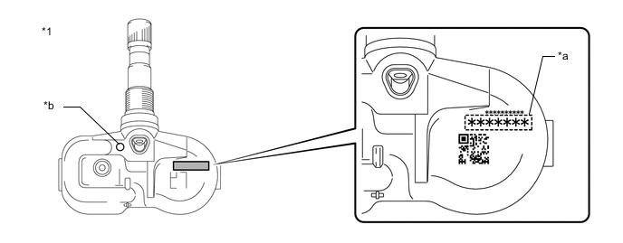
*1 Tire Pressure Warning Valve and Transmitter - - *a Transmitter ID (7-digit Number) *b Wheel Speed Type Tire Inflation Pressure Display Function Identification Mark Note
For vehicles equipped with the wheel speed type tire inflation pressure display function, be sure to use tire pressure warning valve and transmitters with identification marks.
-
Confirm that the ID number on the transmitter and recorded transmitter ID match.
Result Result Proceed to Match A Do not match B
A 
REPLACE CORRESPONDING TIRE PRESSURE WARNING VALVE AND TRANSMITTER Click here
B
GO TO STEP 9 Click here
-
-
TEST MODE INSPECTION (C2181/81 to C2184/84 (C2185/85: w/ Full Size Spare Tire))
-
Perform a test mode inspection and perform Transmitter Data Reception Check (C2181/81 to C2184/84 (C2185/85: w/ Full Size Spare Tire)).
Result Proceed to OK NG
OK
END Explain to the customer that there is a high possibility that a DTC was output due to temporary electrical wave interference.
NG
-
-
CHECK TIRE PRESSURE WARNING VALVE AND TRANSMITTER
-
Turn the ignition switch off.
-
Connect the GTS to the DLC3.
-
Turn the ignition switch to ON.
-
Turn the GTS on.
-
Enter the following menus: Chassis / Tire Pressure Monitor / Data List.
-
Refer to the following chart and record all of the tire pressure warning valve and transmitter IDs.
Chassis > Tire Pressure Monitor > Data ListTester Display Measurement Item Range Normal Condition Diagnostic Note Registered ID 1 Code Registered ID1 code min.: 0
max.: FFFFFFF*1
ID No. registered for transmitter ID1 displayed - Registered ID 2 Code Registered ID2 code min.: 0
max.: FFFFFFF*1
ID No. registered for transmitter ID2 displayed - Registered ID 3 Code Registered ID3 code min.: 0
max.: FFFFFFF*1
ID No. registered for transmitter ID3 displayed - Registered ID 4 Code Registered ID4 code min.: 0
max.: FFFFFFF*1
ID No. registered for transmitter ID4 displayed - Registered ID 5 Code Registered ID5 code min.: 0
max.: FFFFFFF*1
ID No. registered for transmitter ID5 displayed *2 Tech Tips
-
*1: Displayed only when the ID No. is not registered.
-
*2: w/ Full Size Spare Tire
-
The wheel position cannot be determined from ID1 through ID5 on the Data List.
Chassis > Tire Pressure Monitor > Data ListTester Display Registered ID 1 Code Registered ID 2 Code Registered ID 3 Code Registered ID 4 Code Registered ID 5 Code -
-
Disassemble all of the tires and check the tire pressure warning valve and transmitter IDs.

*1 Tire Pressure Warning Valve and Transmitter - - *a Transmitter ID (7-digit Number) *b Wheel Speed Type Tire Inflation Pressure Display Function Identification Mark Note
For vehicles equipped with the wheel speed type tire inflation pressure display function, be sure to use tire pressure warning valve and transmitters with identification marks.
-
Confirm that the ID number on the transmitter and recorded transmitter ID match.
Result Result Proceed to Match A Do not match B
A
REPLACE TIRE PRESSURE WARNING ECU AND RECEIVER Click here
B
-
-
REGISTRATION OF TRANSMITTER ID
-
Perform registration.
Result Proceed to NEXT
NEXT
-
-
PERFORM INITIALIZATION
-
Perform initialization.
Result Proceed to NEXT
NEXT
-
-
CLEAR DTC
-
Clear the DTCs.
Chassis > Tire Pressure Monitor > Clear DTCsResult Proceed to NEXT
NEXT
END
-
-
CLEAR DTC
-
Clear the DTCs.
Chassis > Tire Pressure Monitor > Clear DTCsResult Proceed to NEXT
NEXT
END Explain to the customer that there is a high possibility that a device (located near or inside the vehicle) or facility using electrical waves of approximately the same frequency is causing electrical wave interference.
-