VALVE CLEARANCE ADJUSTMENT
-
REMOVE NO. 2 AIR CLEANER HOSE
-
Disconnect the IAT sensor connector.
-
Loosen the 2 clamps and remove the air cleaner hose.
-
-
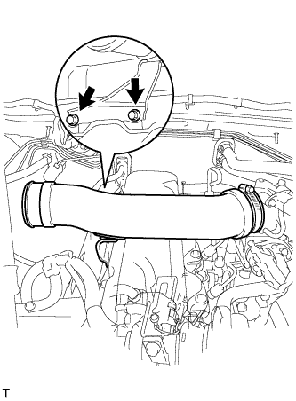
REMOVE INTAKE PIPE ASSEMBLY
-
Loosen the intake pipe clamp.
-
Remove the 2 bolts and intake pipe.
-
-
REMOVE CYLINDER HEAD COVER SUB-ASSEMBLY
-
Disconnect the ventilation hose.
-
Remove the 9 bolts, nut, cylinder head cover and gasket.
-
-
SET NO. 1 CYLINDER TO TDC/COMPRESSION
-
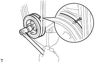
Turn the crankshaft pulley and align its groove with the timing pointer.
-
Check that the valve lifters on the No. 1 cylinder are loose and valve lifters on the No. 4 are tight.
If not, turn the crankshaft one revolution (360°) and align the mark as above.
-
-
INSPECT VALVE CLEARANCE
-
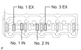
Check only the valves indicated in the illustration.
-
Using a feeler gauge, measure the clearance between the valve lifter and camshaft.
-
Record the out-of-specification valve clearance measurements. They will be used later to determine the required replacement adjusting shim.
Standard valve clearance (Cold) Intake Exhaust 0.20 to 0.30 mm (0.008 to 0.012 in.) 0.40 to 0.50 mm (0.016 to 0.020 in.)
-
-
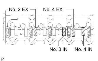
Turn the crankshaft one revolution (360°) and align the mark as above.
-
Check only the valves indicated in the illustration. Measure the valve clearance. (see procedure in the first step)
Standard valve clearance (Cold) Intake Exhaust 0.20 to 0.30 mm (0.008 to 0.012 in.) 0.40 to 0.50 mm (0.016 to 0.020 in.)
-
-
ADJUST VALVE CLEARANCE
-
Remove the adjusting shim.
-
Turn the crankshaft so that the cam lobe of the camshaft on the adjusting valve points upward.
-
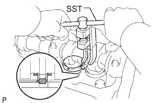
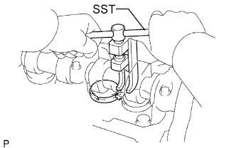
Using SST, press down the valve lifter.
- SST
- 09248-64011
-
Position the notch of the valve lifter with it facing the exhaust manifold side.
-
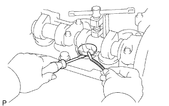
Remove the adjusting shim with a screwdriver and magnetic finger.
-
-
Determine the replacement adjusting shim size by following the formula or charts:
-
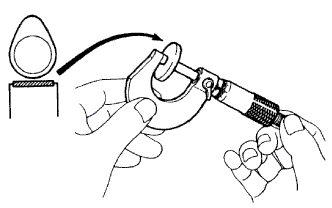
Using a micrometer, measure the thickness of the removed shim.
-
Calculate the thickness of a new shim so that the valve clearance comes within the specified value.
T = Thickness of removed shim
A = Measured valve clearance
N = Thickness of new shim
Intake N = T + (A - 0.25 mm (0.010 in.)) Exhaust N = T + (A - 0.45 mm (0.018 in.)) -
Select a new shim with a thickness as close as possible to the calculated value.
Tech Tips
Shims are available in 17 sizes in increments of 0.05 mm (0.0020 in.), from 2.50 mm (0.0984 in.) to 3.30 mm (0.1299 in.).
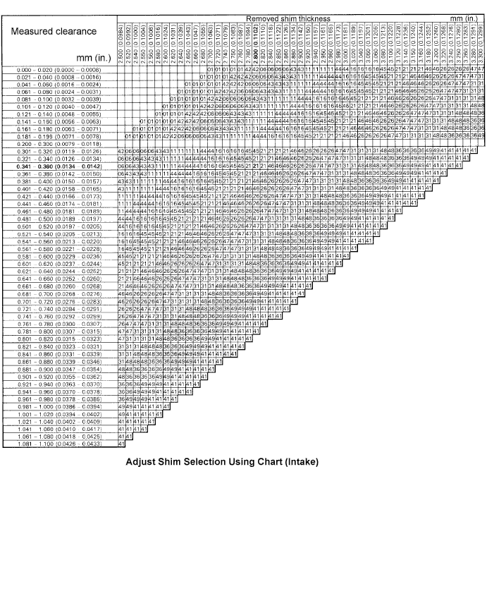
New shim thickness mm (in.) Shim No. Thickness Shim No. Thickness 01 2.50 mm (0.0984 in.) 46 2.95 mm (0.1161 in.) 42 2.55 mm (0.1004 in.) 26 3.00 mm (0.1181 in.) 06 2.60 mm (0.1024 in.) 47 3.05 mm (0.1201 in.) 43 2.65 mm (0.1043 in.) 31 3.10 mm (0.1220 in.) 11 2.70 mm (0.1063 in.) 48 3.15 mm (0.1240 in.) 44 2.75 mm (0.1083 in.) 36 3.20 mm (0.1260 in.) 16 2.80 mm (0.1102 in.) 49 3.25 mm (0.1280 in.) 45 2.85 mm (0.1122 in.) 41 3.30 mm (0.1299 in.) 21 2.90 mm (0.1142 in.) - - Standard intake valve clearance (Cold) 0.20 to 0.30 mm (0.008 to 0.012 in.) EXAMPLE:
The 2.800 mm (0.1102 in.) shim is installed and the measured clearance is 0.350 mm (0.0138 in.). Replace the 2.800 mm (0.1102 in.) shim with a No. 21 shim.
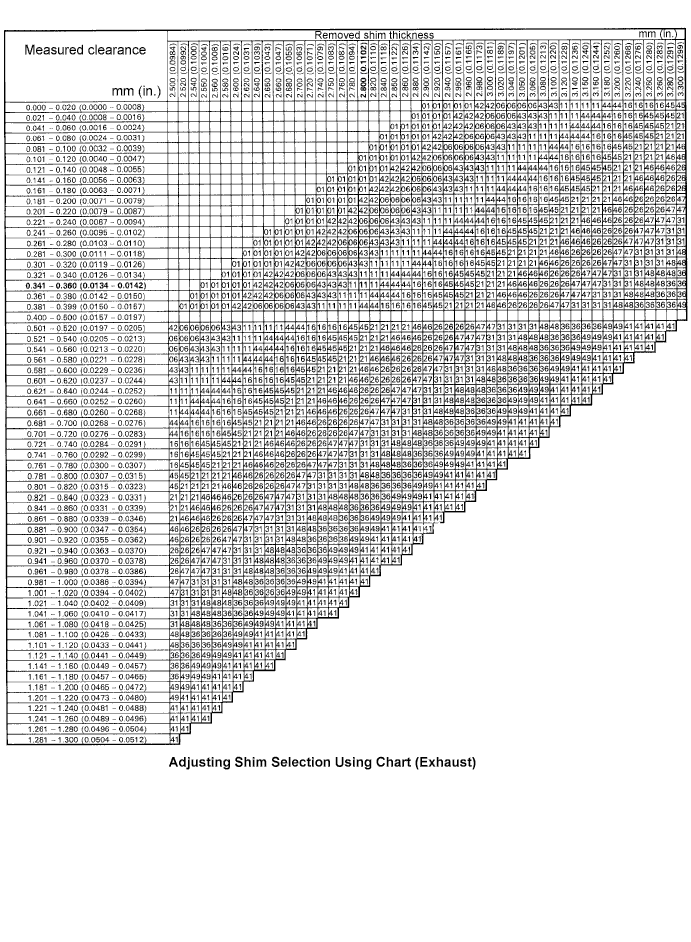
New shim thickness mm (in.) Shim No. Thickness Shim No. Thickness 01 2.50 mm (0.0984 in.) 46 2.95 mm (0.1161 in.) 42 2.55 mm (0.1004 in.) 26 3.00 mm (0.1181 in.) 06 2.60 mm (0.1024 in.) 47 3.05 mm (0.1201 in.) 43 2.65 mm (0.1043 in.) 31 3.10 mm (0.1220 in.) 11 2.70 mm (0.1063 in.) 48 3.15 mm (0.1240 in.) 44 2.75 mm (0.1083 in.) 36 3.20 mm (0.1260 in.) 16 2.80 mm (0.1102 in.) 49 3.25 mm (0.1280 in.) 45 2.85 mm (0.1122 in.) 41 3.30 mm (0.1299 in.) 21 2.90 mm (0.1142 in.) - - Standard exhaust valve clearance (Cold) 0.40 to 0.50 mm (0.016 to 0.020 in.) EXAMPLE:
The 2.800 mm (0.1102 in.) shim is installed and the measured clearance is 0.350 mm (0.0138 in.). Replace the 2.800 mm (0.1102 in.) shim with a No. 11 shim.
-
-
Install a new adjusting shim.
-
Place a new adjusting shim on the valve lifter.
-
Remove the SST.
-
-
Recheck the valve clearance.
-
-
INSTALL CYLINDER HEAD COVER SUB-ASSEMBLY
-
Remove the any oil packing (FIPG) material.
-
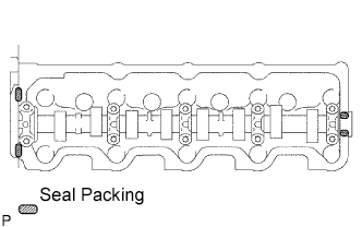
Apply seal packing to the cylinder head as shown in the illustration.
Seal packing Toyota Genuine Seal Packing Black, Three Bond 1207B or equivalent -
Install the gasket to the cylinder head cover.
-
Install the cylinder head cover with the 9 bolts and nut. Uniformly tighten the bolts and nuts in several steps.
- Torque:
- 12 N*m { 120 kgf*cm, 9 ft.*lbf }
-
Connect the ventilation hose.
-
-
INSTALL INTAKE PIPE ASSEMBLY
-
Install the intake pipe with the 2 bolts.
- Torque:
- 18 N*m { 184 kgf*cm, 13 ft.*lbf }
-
Tighten the intake pipe clamp.
-
-
CONNECT NO. 2 AIR CLEANER HOSE
-
Install the air cleaner hose.
-
Tighten the 2 clamps.
-
Connect the IAT sensor connector.
-
-
INSPECT IDLE ENGINE SPEED
-
Warm up the engine.
-
When using the intelligent tester:
-
Connect the intelligent tester to the DLC3.
-
Measure the idle speed.
Standard idle speed 720 to 820 rpm (A/C OFF) 750 to 850 rpm (A/C ON) Tech Tips
Refer to the intelligent tester operator's manual for further details.
-
-
When not using the intelligent tester:
-
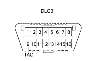
Using SST, connect the tachometer test probe to terminal 9 (TAC) of the DLC3.
- SST
- 09843-18040
-
Measure the idle speed.
Standard idle speed 720 to 820 rpm (A/C OFF) 750 to 850 rpm (A/C ON) Note
Switch off all accessories.
-
-
-
INSPECT MAXIMUM ENGINE SPEED
-
Start the engine.
-
Fully depress the accelerator pedal.
-
Measure the maximum speed.
Maximum speed 4,850 to 4,950 rpm
-