TOE CONTROL LINK REMOVAL

CAUTION / NOTICE / HINT
Tech Tips
-
The procedure listed below is for the LH side.
-
Use the same procedure for the RH and LH sides.
PROCEDURE
-
REMOVE REAR WHEEL
-
REMOVE REAR NO. 1 SUSPENSION ARM ASSEMBLY LH
-
REMOVE TOE CONTROL LINK SUB-ASSEMBLY LH
-
Remove the snap pin.
-
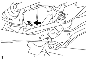
Remove the nut on the rear axle carrier side.
-
Install SST (2 pieces of spacer B) to the threaded section of the t toe control link sub-assembly LH.
- SST
- 09960-20010 ( 09961-02060, 09961-02010 )
-
Using SST (ball join puller), separate the toe control link sub-assembly LH from the rear axle carrier LH.
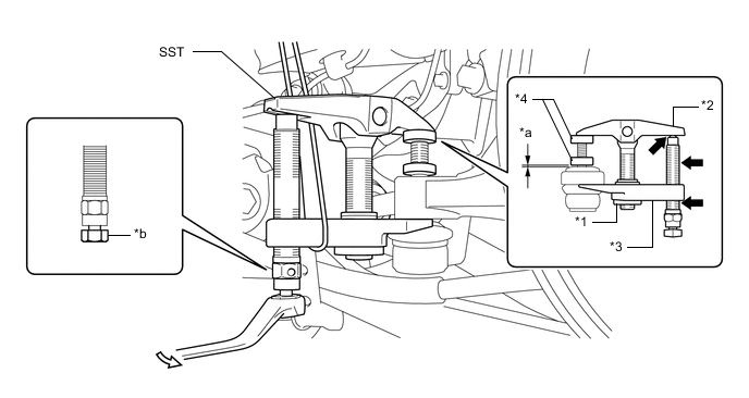
Text in Illustration *1 Nut *2 Body *3 Claw *4 SST (Spacer B) *a 1 mm (0.039 in.) *b Place wrench here 
Molybdenum grease 
Turning direction - SST
- 09960-20010 ( 09961-02060, 09961-02010 )
CAUTION:
Before working, apply molybdenum grease to the bolt threads and bolt tip of SST.
Note
-
As the dust cover may be damaged, adjust SST with the center nut so that the body and claw are parallel.
-
Make sure to tie the string of SST to the vehicle to prevent SST from dropping.
-
Do not damage the dust cover on the toe control link sub-assembly.
-
Do not damage the toe control link sub-assembly.
-
Do not damage the parking brake plate sub-assembly.
-
Do not damage the rear axle carrier.
-
Put matchmarks on the rear No. 2 suspension toe adjust plate and the rear suspension member.
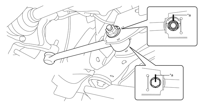
Text in Illustration *a Matchmark - - -
Remove the nut, toe adjust cam, rear No. 2 suspension toe adjust plate and the toe control link sub-assembly.
-