ENGINE IMMOBILISER SYSTEM TERMINALS OF ECU
-
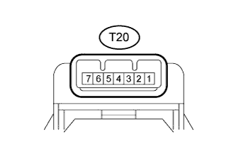
CHECK TRANSPONDER KEY AMPLIFIER
-
Measure the resistance and voltage according to the value(s) in the table below.
Inspection with Ignition Switch Off Terminal No. (Symbol) Input/Output Wiring Color Terminal Description Condition Specified Condition Related Data List Item/DTC T20-7 (AGND) - Body ground - L-O - Body ground Ground Always Below 1 Ω - T20-1 (VC5) - T20-7 (AGND) Input L - L-O Transponder key amplifier power supply No key in ignition key cylinder Below 1 V - T20-4 (CODE) - T20-7 (AGND) Output L-Y - L-O Demodulated signal of key code data No key in ignition key cylinder Below 1 V - T20-5 (TXCT) - T20-7 (AGND) Input L-B - L-O Key code output signal No key in ignition key cylinder Below 1 V -
-
If the result is not as specified, there may be a malfunction on the wire harness side.
Inspection of Waveforms of Communication Signals between Transponder Key Amplifier and Transponder Key ECU Assembly Terminal No. (Symbol) Input/Output Wiring Color Terminal Description Condition Specified Condition Related Data List Item/DTC T20-1 (VC5) - T20-7 (AGND) Input L - L-O Transponder key amplifier power supply No key in ignition key cylinder Below 1 V
-
BCC Malfunction
-
Abnormal Status
-
Different Encrypt Code
-
Different Serial Number
(If immobiliser key code certification communication is not performed correctly, the malfunction may be indicated by one or more of the Data List items listed above)
Key inserted in ignition key cylinder 4.6 to 5.4 V T20-4 (CODE) - T20-7 (AGND) Output L-Y - L-O Demodulated signal of key code data No key in ignition key cylinder Below 1 V Key inserted in ignition key cylinder Pulse generation (See waveform 1) T20-5 (TXCT) - T20-7 (AGND) Input L-B - L-O Key code output signal No key in ignition key cylinder Below 1 V Key inserted in ignition key cylinder Pulse generation (See waveform 2)
-
If the result is not as specified, the amplifier may have a malfunction.
-
-
Inspect using an oscilloscope.
Tech Tips
The waveform shown in the illustration is an example for reference only. Noise, chattering, etc. are not shown.
-
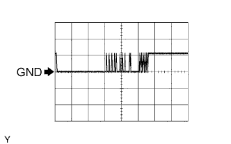
Waveform 1 (Reference)
Measurement Condition Item Content Tester Connection T20-4 (CODE) - T20-7 (AGND) Tool Setting 5 V/DIV., 20 ms./DIV. Condition Key inserted in ignition key cylinder -
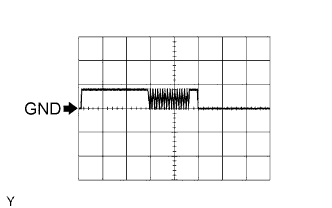
Waveform 2 (Reference)
Measurement Condition Item Content Tester Connection T20-5 (TXCT) - T20-7 (AGND) Tool Setting 5 V/DIV., 20 ms./DIV. Condition Key inserted in ignition key cylinder
-
-
-
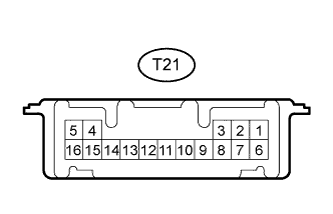
CHECK TRANSPONDER KEY ECU ASSEMBLY
-
Disconnect the T21 transponder key ECU assembly connector.
-
Measure the resistance and voltage according to the value(s) in the table below.
Terminal No. (Symbol) Input/Output Wiring Color Terminal Description Condition Specified Condition Related Data List Item/DTC T21-16 (GND) - Body ground - G - Body ground Ground Always Below 1 Ω - T21-1 (+B) - T21-16 (GND) Input L-Y - G Battery Always 11 to 14 V +B T21-2 (IG) - T21-16 (GND) Input B-O - G Ignition switch Ignition switch off Below 1 V IG SW Ignition switch ON 11 to 14 V T21-3 (KSW) - T21-16 (GND) Input BR - G Unlock warning switch No key in ignition key cylinder 10 kΩ or higher Key SW/B2780 Key inserted in ignition key cylinder Below 1 Ω
-
If the result is not as specified, there may be a malfunction on the wire harness side.
-
-
Reconnect the T21 transponder key ECU assembly connector.
-
Measure the resistance and voltage according to the value(s) in the table below.
Terminal No. (Symbol) Input/Output Wiring Color Terminal Description Condition Specified Condition Related Data List Item/DTC T21-14 (VC5) - T21-16 (GND) Input L - G Transponder key amplifier power supply No key in ignition key cylinder Below 1 V
-
BCC Malfunction
-
Abnormal Status
-
Different Encrypt Code
-
Different Serial Number
(If immobiliser key code certification communication is not performed correctly, the malfunction may be indicated by one or more of the Data List items listed above)
Key inserted in ignition key cylinder 4.6 to 5.4 V T21-4 (TXCT) - T21-16 (GND) Input L-B - G Key code output signal No key in ignition key cylinder Below 1 V Key inserted in ignition key cylinder Pulse generation (See waveform 1) T21-15 (CODE) - T21-16 (GND) Output L-Y - G Demodulated signal of key code data No key in ignition key cylinder Below 1 V Key inserted in ignition key cylinder Pulse generation (See waveform 2) T21-7 (CTY) - T21-16 (GND) Input R-B - G Front door courtesy light switch (for Driver Side) Driver door closed 10 kΩ or higher D Door Courtesy SW Driver door open Below 1 Ω T21-13 (EFIO) - T21-16 (GND) Input Y-G - G ECM output signal Ignition switch off Below 1 V E/G Start Permission Ignition switch ON Pulse generation (See waveform 3) T21-12 (EFII) - T21-16 (GND) Output Y-B - G ECM input signal Within 3 seconds after starter operates and initial combustion occurs, or within 3 seconds after ignition switch first turned to ON after battery disconnected and reconnected Pulse generation (See waveform 4) E/G Start Permission T21-8 (IND) - T21-16 (GND) Output G-R - G Security indicator light signal Immobiliser set Alternating between 11 to 14 V and below 1 V - Immobiliser unset Below 1 V T21-9 (D) - T21-16 (GND) Input/Output B - G Diagnosis tester communication Always Pulse generation - T21-5 (AGND) - Body ground - L-O - Body ground Transponder key amplifier ground Always Below 1 Ω -
-
If the result is not as specified, the ECU may have a malfunction.
-
-

Inspect using an oscilloscope.
Tech Tips
The waveform shown in the illustration is an example for reference only. Noise, chattering, etc. are not shown.
-
Waveform 1 (Reference)
Measurement Condition Item Content Tester Connection T21-4 (TXCT) - T21-16 (GND) Tool Setting 5 V/DIV., 20 ms./DIV. Condition Key inserted in ignition key cylinder -

Waveform 2 (Reference)
Measurement Condition Item Content Tester Connection T21-15 (CODE) - T21-16 (GND) Tool Setting 5 V/DIV., 20 ms./DIV. Condition Key inserted in ignition key cylinder -
Waveform 3 (Reference)
Measurement Condition Item Content Tester Connection T21-13 (EFIO) - T21-16 (GND) Tool Setting 10 V/DIV., 100 ms./DIV. Condition Ignition switch ON -
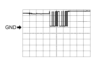
Waveform 4 (Reference)
Measurement Condition Item Content Tester Connection T21-12 (EFII) - T21-16 (GND) Tool Setting 5 V/DIV., 500 ms./DIV. Condition Within 3 seconds after starter operates and initial combustion occurs, or within 3 seconds after ignition switch first turned to ON after battery disconnected and reconnected
-
-
-
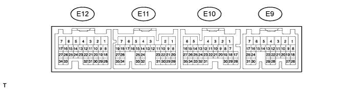
CHECK ECM (for 1TR-FE, 2TR-FE)
-
Measure the voltage according to the value(s) in the table below.
Terminal No. (Symbol) Wiring Color Terminal Description Condition Specified Condition E10-15 (IMO) - Body ground Y-B - Body ground Transponder key ECU assembly output signal Within 3 seconds after starter operates and initial combustion occurs, or within 3 seconds after ignition switch first turned ON after battery disconnected and connected. Pulse generation (See waveform 1) E10-16 (IMI) - Body ground Y-G -Body ground Transponder key ECU assembly input signal Ignition switch off Below 1 V Ignition switch ON Pulse generation (See waveform 2)
-
If the result is not as specified, the ECM may have a malfunction.
-
-
Inspect using an oscilloscope.
Tech Tips
The waveform shown in the illustration is an example for reference only. Noise, chattering, etc. are not shown.
-
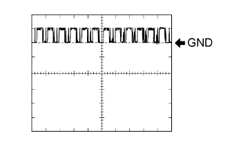
Waveform 1 (Reference)
Measurement Condition Item Content Tester Connection E10-15 (IMO) - Body ground Tool Setting 5 V/DIV., 500 ms./DIV. Condition Within 3 seconds after starter operates and initial combustion occurs, or within 3 seconds after ignition switch first turned ON after battery disconnected and connected. -
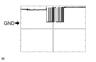
Waveform 2 (Reference)
Measurement Condition Item Content Tester Connection E10-16 (IMI) - Body ground Tool Setting 10 V/DIV., 100 ms./DIV. Condition Ignition switch ON
-
-
-
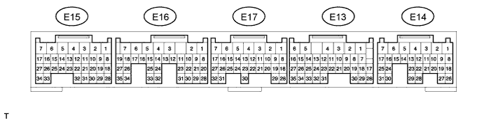
CHECK ECM (for 1GR-FE)
-
Measure the voltage according to the value(s) in the table below.
Terminal No. (Symbol) Wiring Color Terminal Description Condition Specified Condition E13-15 (IMO) - Body ground Y-B - Body ground Transponder key ECU assembly output signal Within 3 seconds after starter operates and initial combustion occurs, or within 3 seconds after ignition switch first turned ON after battery disconnected and connected. Pulse generation (See waveform 1) E13-16 (IMI) - Body ground Y-G -Body ground Transponder key ECU assembly input signal Ignition switch off Below 1 V Ignition switch ON Pulse generation (See waveform 2)
-
If the result is not as specified, the ECM may have a malfunction.
-
-
Inspect using an oscilloscope.
Tech Tips
The waveform shown in the illustration is an example for reference only. Noise, chattering, etc. are not shown.
-
Waveform 1 (Reference)
Measurement Condition Item Content Tester Connection E13-15 (IMO) - Body ground Tool Setting 5 V/DIV., 500 ms./DIV. Condition Within 3 seconds after starter operates and initial combustion occurs, or within 3 seconds after ignition switch first turned ON after battery disconnected and connected. -
Waveform 2 (Reference)
Measurement Condition Item Content Tester Connection E13-16 (IMI) - Body ground Tool Setting 10 V/DIV., 100 ms./DIV. Condition Ignition switch ON
-
-
-
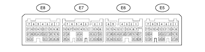
CHECK ECM (for 1KD-FTV, 2KD-FTV) (except DPF)
-
Measure the voltage according to the value(s) in the table below.
Terminal No. (Symbol) Wiring Color Terminal Description Condition Specified Condition E6-29 (IMO) - Body ground Y-B - Body ground Transponder key ECU assembly output signal Within 3 seconds after starter operates and initial combustion occurs, or within 3 seconds after ignition switch first turned ON after battery disconnected and connected. Pulse generation (See waveform 1) E6-30 (IMI) - Body ground Y-G -Body ground Transponder key ECU assembly input signal Ignition switch off Below 1 V Ignition switch ON Pulse generation (See waveform 2)
-
If the result is not as specified, the ECM may have a malfunction.
-
-
Inspect using an oscilloscope.
Tech Tips
The waveform shown in the illustration is an example for reference only. Noise, chattering, etc. are not shown.
-
Waveform 1 (Reference)
Measurement Condition Item Content Tester Connection E6-29 (IMO) - Body ground Tool Setting 5 V/DIV., 500 ms./DIV. Condition Within 3 seconds after starter operates and initial combustion occurs, or within 3 seconds after ignition switch first turned ON after battery disconnected and connected. -
Waveform 2 (Reference)
Measurement Condition Item Content Tester Connection E6-30 (IMI) - Body ground Tool Setting 10 V/DIV., 100 ms./DIV. Condition Ignition switch ON
-
-
-
CHECK ECM (for 1KD-FTV, 2KD-FTV) (for DPF)
-
Measure the voltage according to the value(s) in the table below.
Terminal No. (Symbol) Wiring Color Terminal Description Condition Specified Condition E30-29 (IMO) - Body ground Y-B - Body ground Transponder key ECU assembly output signal Within 3 seconds after starter operates and initial combustion occurs, or within 3 seconds after ignition switch first turned ON after battery disconnected and connected. Pulse generation (See waveform 1) E30-28 (IMI) - Body ground Y-G -Body ground Transponder key ECU assembly input signal Ignition switch off Below 1 V Ignition switch ON Pulse generation (See waveform 2)
-
If the result is not as specified, the ECM may have a malfunction.
-
-
Inspect using an oscilloscope.
Tech Tips
The waveform shown in the illustration is an example for reference only. Noise, chattering, etc. are not shown.
-
Waveform 1 (Reference)
Measurement Condition Item Content Tester Connection E30-29 (IMO) - Body ground Tool Setting 5 V/DIV., 500 ms./DIV. Condition Within 3 seconds after starter operates and initial combustion occurs, or within 3 seconds after ignition switch first turned ON after battery disconnected and connected. -
Waveform 2 (Reference)
Measurement Condition Item Content Tester Connection E30-28 (IMI) - Body ground Tool Setting 10 V/DIV., 100 ms./DIV. Condition Ignition switch ON
-
-