DIFFERENTIAL CARRIER ASSEMBLY REASSEMBLY
-
ASSEMBLE DIFFERENTIAL CASE (for 2 Pinion Gear Type)
-
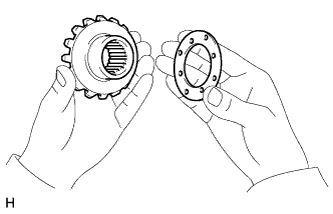
Install the side gear thrust washer to the side gear.
Tech Tips
Using the table below, select 2 thrust washers which will ensure that the backlash is within the specifications.
Standard Washer Thickness Thickness mm (in.) Thickness mm (in.) 1.48 to 1.52 (0.0583 to 0.0598) 1.73 to 1.77 (0.0682 to 0.0696) 1.53 to 1.57 (0.0603 to 0.0618) 1.78 to 1.82 (0.0701 to 0.0716) 1.58 to 1.62 (0.0622 to 0.0637) 1.83 to 1.87 (0.0721 to 0.0736) 1.63 to 1.67 (0.0642 to 0.0657) 1.88 to 1.92 (0.0741 to 0.0755) 1.68 to 1.72 (0.0662 to 0.0677) - -
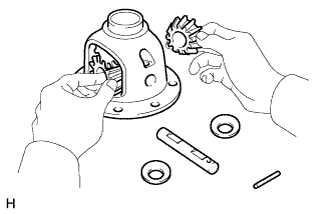
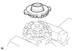
Install 2 side gears, 2 pinion gears, 2 side gear thrust washers, 2 pinion gear thrust washers and the pinion shaft in the differential case.
Tech Tips
Align the holes of the differential case and pinion shaft.
-
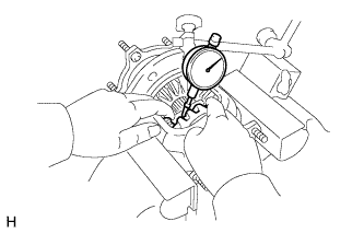
Measure the side gear backlash.
-
Using a dial indicator, measure the side gear backlash while holding one pinion gear toward the differential case.
Backlash 0.05 to 0.20 mm (0.00197 to 0.00787 in.)
-
If the backlash is not as specified, install 2 side gear thrust washers with different thicknesses.
-
-
-
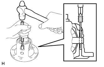
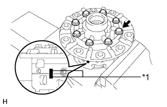
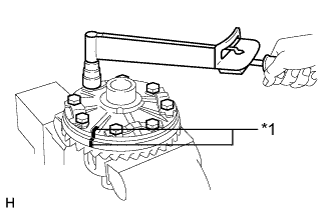
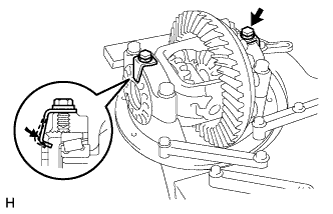
Using a pin punch and hammer, tap in the straight pin through the differential case and hole of the pinion shaft.
-
Stake the differential case.
-
-
ASSEMBLE DIFFERENTIAL CASE (for LSD)
-
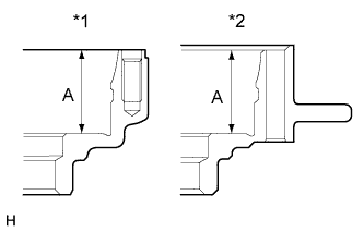
Text in Illustration *1 Case RH *2 Case LH Measure the differential case dimension labeled A.
-
Install the thrust washers and clutch plates on the side gear.
-
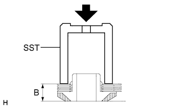
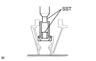
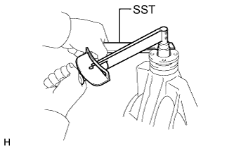
Using SST to press down the thrust washers and clutch plates with a force of approximately 98 N*m (1000 kgf*cm, 72 ft.*lbf), measure dimension "B" shown in the illustration.
- SST
- 09649-17010
-
Referring to the following table, select the proper adjusting shim.
Adjusting shim thickness Adjusting shim thickness = A - B - 16.175 mm (0.637 in.) Thickness mm (in.) Thickness mm (in.) 1.83 to 1.89 (0.0721 to 0.0744) 2.19 to 2.25 (0.0863 to 0.0885) 1.89 to 1.95 (0.0745 to 0.0767) 2.25 to 2.31 (0.0886 to 0.0909) 1.95 to 2.01 (0.0768 to 0.0791) 2.31 to 2.37 (0.0910 to 0.0933) 2.01 to 2.07 (0.0792 to 0.0814) 2.37 to 2.43 (0.0934 to 0.0956) 2.07 to 2.13 (0.0815 to 0.0838) 2.43 to 2.49 (0.0957 to 0.0980) 2.13 to 2.19 (0.0839 to 0.0862) - -
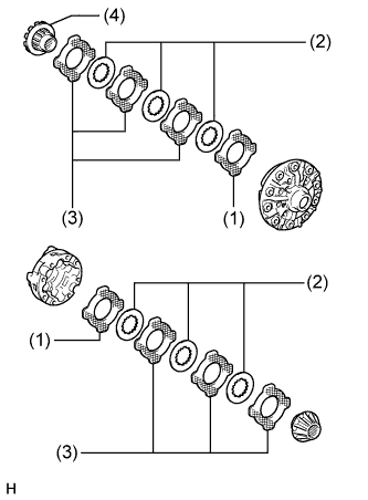
Install the following parts to the differential cases.
-
(1) Side gear thrust washer
-
(2) Clutch plate
-
(3) No. 1 side gear thrust washer
-
(4) Side gear
-
-
Install the 4 pinion gears and thrust washers to the spider.
-
Align the spring RH retainer holes with the spider knock pins and install the RH retainer.
-
Install the pinion gears and spider to the differential RH case.
Tech Tips
Install the spider to the RH case tightly and do not move the spring retainer.
-
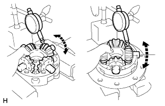
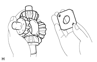
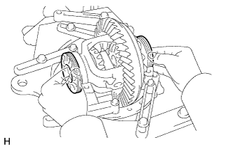
Using a dial indicator, measure the side gear backlash while holding the side gear spider.
Backlash 0.05 to 0.20 mm (0.00197 to 0.00787 in.)
-
If the backlash is not within the specification, install an adjusting shim of a different thickness.
Tech Tips
-
Measure at all 4 locations.
-
Measure the backlash at the LH case and at the RH case.
-
-
-
Reinstall the spider to the RH case tightly and do not move the spring retainer.
-
Install the compression spring and spring LH retainer.
-
Install the side gear, thrust washers and clutch plates.
-
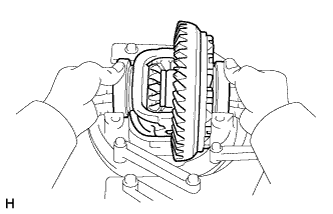
Align the matchmarks and assemble the RH and LH cases.
Tech Tips
Be careful not to drop the side gear and check the pinion and side gear alignment.
-
Text in Illustration *1 Matchmark Align the matchmarks on the differential case RH and differential case LH.
-
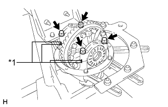
Install the 8 bolts by diametrically tightening the bolts uniformly in several passes.
- Torque:
- 47 N*m { 480 kgf*cm, 35 ft.*lbf }
-
-
INSTALL DIFFERENTIAL RING GEAR
-
Clean the contact surfaces of the differential case and ring gear.
-
Heat the ring gear in boiling water that is approximately 100°C (212°F).
-
Carefully remove the ring gear from the boiling water.
-
Text in Illustration *1 Matchmark After the moisture on the ring gear has completely evaporated, quickly align the matchmarks on the ring gear and differential case and install the ring gear to the differential case.
-
Temporarily install 5 new lock plates and the 10 bolts.
-
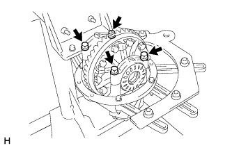
After the ring gear cools down, install the 10 bolts by diametrically tightening the bolts uniformly in several passes.
- Torque:
- 87 N*m { 891 kgf*cm, 64 ft.*lbf }
-
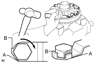
Using a chisel and hammer, stake the 5 lock plates.
Tech Tips
Strike the tab labeled A so that it is flush with the flat surface of the bolt. Strike the tab labeled B so that half of the tab contacts the bolt as shown in the illustration.
-
-
INSTALL REAR DIFFERENTIAL CASE BEARING
-
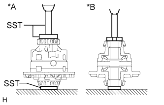
Text in Illustration *A for LSD *B 2 Pinion Type Using SST and a press, press the bearing onto the differential case.
- SST
- 09950-60010 ( 09951-00430, 09951-00470, 09951-00480, 09951-00550 )
- 09950-70010 ( 09951-00560, 09951-00570, 09951-07150 )
-
-
INSPECT DIFFERENTIAL RING GEAR RUNOUT
-
Install the differential case on the carrier, and install the 2 adjusting nuts so that there is no play in the bearing.
-
Install the 2 bearing caps with the 4 bolts.
- Torque:
- 85 N*m { 870 kgf*cm, 63 ft.*lbf }
-
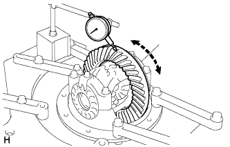
Using a dial indicator, measure the runout of the ring gear.
Maximum runout 0.07 mm (0.0028 in.) -
Remove the 2 bearing caps, 2 adjusting nuts and differential case.
-
-
INSTALL REAR DRIVE PINION FRONT TAPERED ROLLER BEARING
-
Using SST and a press, press the roller bearing (outer) to the carrier.
- SST
- 09316-60011 ( 09316-00011, 09316-00021 )
-
-
INSTALL REAR DRIVE PINION REAR TAPERED ROLLER BEARING
-
Using SST and a press, press the roller bearing (outer) into the carrier.
- SST
- 09316-60011 ( 09316-00011, 09316-00041 )
-
-
INSTALL REAR DRIVE PINION REAR TAPERED ROLLER BEARING
-
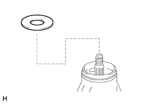
Install the plate washer to the drive pinion.
Tech Tips
First, install a washer that has the same thickness as the removed washer. After checking the tooth contact pattern, replace the washer with one of a different thickness if necessary.
-
Using SST and a press, press the roller bearing (inner) onto the drive pinion.
- SST
- 09506-30012
-
-
ADJUST DIFFERENTIAL DRIVE PINION PRELOAD
-
Install the drive pinion, rear drive pinion tapered roller bearing and rear differential drive pinion oil slinger.
Tech Tips
Install the spacer and oil seal after adjusting the gear contact pattern.
-
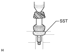
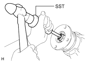
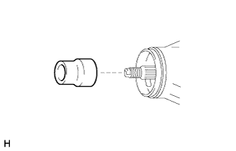
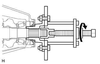
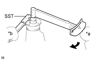
Text in Illustration *a Turn *b Hold Using SST, install the companion flange.
- SST
- 09950-30012 ( 09951-03010, 09953-03010, 09954-03010, 09955-03030, 09956-03040 )
Note
Before using SST (center bolt), apply hypoid gear oil to its threads and tip.
-
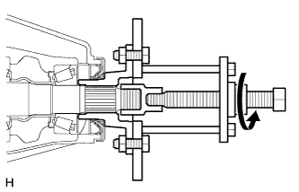
Adjust the drive pinion preload by tightening the companion flange nut.
-
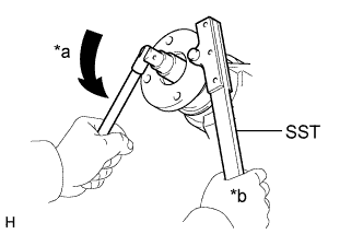
Using SST to hold the companion flange in place, tighten the nut.
- SST
- 09330-00021 ( 09330-00030 )
- Torque:
- 370 N*m { 3773 kgf*cm, 273 ft.*lbf, or less }
Note
-
As there is no spacer, tighten a little at a time. Be careful not to overtighten the nut.
-
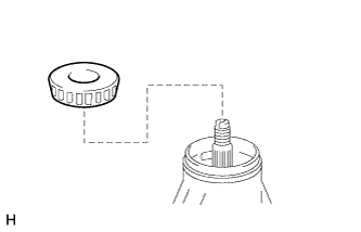
Apply hypoid gear oil LSD to drive pinion thread and nut seat face.
-
Using a torque wrench, measure the preload.
Standard Drive Pinion Preload (Starting Torque) Bearing Preload New bearing 1.0 to 1.5 N*m (11 to 15 kgf*cm, 9 to 13 in.*lbf) Reused bearing 0.5 to 0.7 N*m (6 to 7 kgf*cm, 5 to 6 in.*lbf) Note
-
For a more accurate measurement, rotate the bearing forward and backward several times before measuring.
-
Record the differential drive pinion preload for the total preload measurement.
-
-
-
INSTALL DIFFERENTIAL CASE ASSEMBLY
-
Place the 2 bearing outer races to their respective bearings.
Tech Tips
Make sure the right and left races are not interchanged.
-
-
INSTALL REAR DIFFERENTIAL BEARING ADJUSTING NUT
-
Install the 2 adjusting nuts to the carrier, making sure the nuts are threaded properly.
-
-
INSPECT AND ADJUST DIFFERENTIAL RING GEAR AND DIFFERENTIAL DRIVE PINION BACKLASH
-
Text in Illustration *1 Matchmark Align the matchmarks on the cap and carrier.
-
Install the right and left bearing caps with the 4 bolts.
- Torque:
- 85 N*m { 870 kgf*cm, 63 ft.*lbf }
-
If the bearing cap does not fit tightly on the carrier, the adjusting nuts are not threaded properly.
Tech Tips
Reinstall the adjusting nuts if necessary.
-
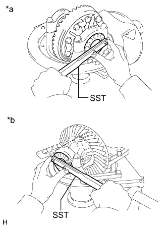
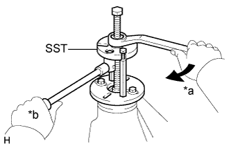
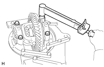
Text in Illustration *a for LH Side *b for RH Side Loosen the 4 bearing cap bolts to the point where the adjusting nuts can be turned by SST.
-
Using SST, torque the adjusting nut on the ring gear side until the ring gear has a backlash of about 0.2 mm (0.00787 in.).
- SST
- 09504-00011
- 09960-10010 ( 09962-01000, 09963-00700 )
-
While turning the ring gear, use SST to tighten the adjusting nut on the drive pinion side. After the bearings have settled, loosen the adjusting nut on the drive pinion side.
-
Using SST, tighten the adjusting nut 1 to 1.5 notches from the 0 preload position.
- SST
- 09504-00011
- 09960-10010 ( 09962-01000, 09963-00700 )
-
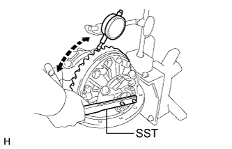
Using a dial indicator, adjust the ring gear backlash until it is within the specification.
Standard backlash 0.13 to 0.18 mm (0.00512 to 0.00708 in.) Tech Tips
-
The backlash is adjusted by turning the left and right adjusting nuts an equal amount. For example, loosen the nut on the right side one notch and loosen the nut on the left side one notch.
-
Perform the measurement at 3 or more positions around the circumference of the ring gear.
-
-
Tighten the bearing cap bolts.
- Torque:
- 85 N*m { 870 kgf*cm, 63 ft.*lbf }
-
-
INSPECT TOTAL PRELOAD
-
Using a torque wrench, measure the preload with the teeth of the drive pinion and ring gear in contact.
-
Using a torque wrench, measure the total preload.
Standard Total Preload Item Specified Condition New bearing 0.4 to 0.5 N*m (4 to 6 kgf*cm, 4 to 5 in.*lbf) + drive pinion preload Reused bearing 0.4 to 0.5 N*m (4 to 6 kgf*cm, 4 to 5 in.*lbf) + drive pinion preload If necessary, disassemble and inspect the differential.
Note
Record the differential ring gear preload.
-
-
INSPECT TOOTH CONTACT BETWEEN RING GEAR AND DRIVE PINION
-
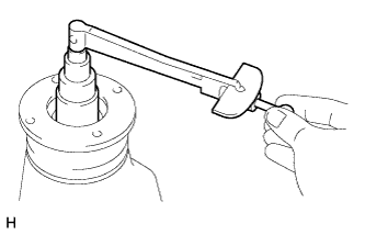
Coat 3 or 4 teeth at 3 different positions on the ring gear with Prussian blue.
-
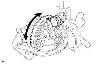
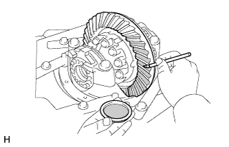
Hold the companion flange firmly in place and rotate the ring gear in both directions.
-
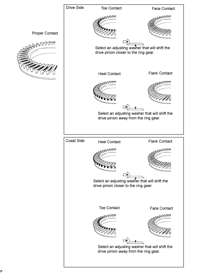
Inspect the tooth contact pattern.
-
-
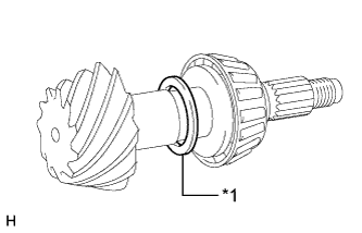
Text in Illustration *1 Plate Washer If the teeth are not contacting properly, use the following chart to select a proper washer.
Standard Plate Washer Thickness Thickness mm (in.) Thickness mm (in.) 1.69 to 1.71 (0.0666 to 0.0673) 2.02 to 2.04 (0.0796 to 0.0803) 1.72 to 1.74 (0.0678 to 0.0685) 2.05 to 2.07 (0.0807 to 0.0814) 1.75 to 1.77 (0.0689 to 0.0696) 2.08 to 2.10 (0.0819 to 0.0826) 1.78 to 1.80 (0.0701 to 0.0708) 2.11 to 2.13 (0.0831 to 0.0838) 1.81 to 1.83 (0.0713 to 0.0720) 2.14 to 2.16 (0.0843 to 0.0850) 1.84 to 1.86 (0.0725 to 0.0732) 2.17 to 2.19 (0.0855 to 0.0862) 1.87 to 1.89 (0.0737 to 0.0744) 2.20 to 2.22 (0.0867 to 0.0874) 1.90 to 1.92 (0.0748 to 0.0755) 2.23 to 2.25 (0.0878 to 0.0885) 1.93 to 1.95 (0.0760 to 0.0767) 2.26 to 2.28 (0.0890 to 0.0897) 1.96 to 1.98 (0.0772 to 0.0779) 2.29 to 2.31 (0.0902 to 0.0909) 1.99 to 2.01 (0.0784 to 0.0791) 2.32 to 2.34 (0.0914 to 0.0921)
-
-
-
REMOVE REAR DRIVE PINION NUT
-
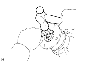
Using SST and a hammer, loosen the staked part of the nut.
- SST
- 09930-00010 ( 09931-00010, 09931-00020 )
-
Text in Illustration *a Turn *b Hold Using SST to hold the companion flange in place, remove the nut.
- SST
- 09330-00021 ( 09330-00030 )
-
-
REMOVE REAR DRIVE PINION COMPANION FLANGE SUB-ASSEMBLY WITH DUST DEFLECTOR
-
Using SST, remove the companion flange with dust deflector.
- SST
- 09950-30012 ( 09951-03010, 09953-03010, 09954-03010, 09955-03030, 09956-03040 )
Note
Before using SST (center bolt), apply hypoid gear oil to its threads and tip.
-
-
REMOVE REAR DIFFERENTIAL DRIVE PINION OIL SLINGER
-
Remove the oil slinger from the drive pinion.
-
-
REMOVE REAR DRIVE PINION FRONT TAPERED ROLLER BEARING
-

Using SST, remove the roller bearing (inner) from the drive pinion.
- SST
- 09556-22010
-
-
INSTALL REAR DIFFERENTIAL DRIVE PINION BEARING SPACER
-
Install a new bearing spacer.
Tech Tips
Make sure the spacer is installed correctly.
-
-
INSTALL DIFFERENTIAL OIL STORAGE RING
-
Using a brass bar and hammer, tap in a new oil storage ring.
Note
Be careful not to damage the oil storage ring.
-
-
INSTALL REAR DRIVE PINION FRONT TAPERED ROLLER BEARING
-
Install the bearing (inner) to the drive pinion.
-
-
INSTALL REAR DIFFERENTIAL DRIVE PINION OIL SLINGER
-
Install the oil slinger to the drive pinion.
-
-
INSTALL REAR DIFFERENTIAL CARRIER OIL SEAL
-
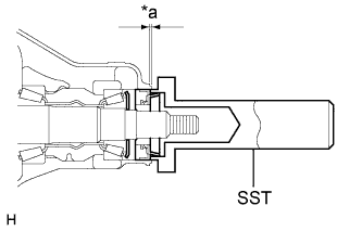
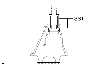
Text in Illustration *a Oil Seal Depth Using SST and a hammer, tap in a new oil seal.
- SST
- 09554-30011
Standard oil seal depth 0 +/-0.3mm (0 +/-0.0118in.) -
Apply MP grease to the lip of the oil seal.
-
-
INSTALL REAR DRIVE PINION COMPANION FLANGE SUB-ASSEMBLY WITH DUST DEFLECTOR
-
Using SST, install the companion flange with dust deflector.
- SST
- 09950-30012 ( 09951-03010, 09953-03010, 09954-03010, 09955-03030, 09956-03040 )
Note
Before using SST (center bolt), apply hypoid gear oil to its threads and tip.
-
Apply hypoid gear oil LSD to drive pinion thread and nut seat face.
-
Text in Illustration *a Turn *b Hold Using SST to hold the companion flange in place, install a new nut.
- SST
- 09330-00021 ( 09330-00030 )
- Torque:
- 370 N*m { 3773 kgf*cm, 273 ft.*lbf, or less }
-
-
INSPECT TOTAL PRELOAD
-
Using a torque wrench, measure the preload with the teeth of the drive pinion and ring gear in contact.
-
Using a torque wrench, measure the total preload.
Standard Total Preload Bearing Preload New bearing 1.1 to 1.6 N*m (12 to 16 kgf*cm, 10 to 14 in.*lbf) + ring gear preload Reused bearing 0.6 to 0.8 N*m (7 to 8 kgf*cm, 6 to 7 in.*lbf) + ring gear preload
-
If necessary, disassemble and inspect the differential.
-
-
-
INSPECT DIFFERENTIAL RING GEAR BACKLASH
-
Using a dial indicator, check the backlash of the ring gear.
Standard backlash 0.13 to 0.18 mm (0.00512 to 0.00708 in.)
-
If the backlash is not as specified, adjust the side bearing preload or perform repairs as necessary.
Tech Tips
Perform the measurement at 3 or more positions around the circumference of the ring gear.
-
-
-
INSPECT RUNOUT OF REAR DRIVE PINION COMPANION FLANGE SUB-ASSEMBLY
-
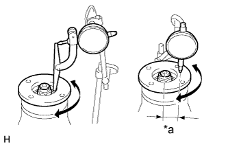
Text in Illustration *a 30 mm (1.18 in.) Using a dial indicator, measure the runout of the companion flange vertically and laterally.
Maximum Runout Runout Maximum Vertical runout 0.10 mm (0.00394 in.) Lateral runout 0.10 mm (0.00394 in.)
-
If the runout is more than the maximum, replace the companion flange.
-
-
-
STAKE DRIVE PINION NUT
-
Using a chisel and hammer, stake the nut.
-
-
INSTALL REAR DIFFERENTIAL BEARING ADJUSTING NUT LOCK
-
Install 2 new adjusting nut locks to the bearing caps with the 2 bolts.
- Torque:
- 13 N*m { 130 kgf*cm, 9 ft.*lbf }
-
Bend the nut locks.
-