CONTINUOUSLY VARIABLE TRANSAXLE ASSEMBLY(When Not Using the Engine Support Bridge) REMOVAL

CAUTION / NOTICE / HINT
The necessary procedures (adjustment, calibration, initialization, or registration) that must be performed after parts are removed, installed, or replaced during the continuously variable transaxle assembly removal/installation are shown below.
| Replacement Part or Procedure | Necessary Procedure | Effect/Inoperative when not Performed | Link |
|---|---|---|---|
| Disconnect cable from negative battery terminal | Memorize steering angle neutral point |
|
|
| Initialize back door lock | Power door lock control system | ||
|
Inspection After Repair |
|
|
| Replacement of CVT fluid | ATF thermal degradation estimate reset | The value of the Data List item "ATF Thermal Degradation Estimate" is not estimated correctly | |
| Replacement of continuously variable transaxle assembly | Perform the following procedures in the order shown:
|
Deterioration of fuel efficiency | |
| Front wheel alignment adjustment | Perform the following procedures in the order shown:
|
|
|
| Suspension, tires, etc. (The vehicle height changes because of suspension or tire replacement) |
Initialize No. 1 headlight ECU sub-assembly LH | Automatic headlight beam level control system |
-
*1: When performing learning using the GTS.
CAUTION:
-
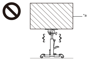
*a Heavy object exceeding the capacity of the transmission jack Because the continuously variable transaxle assembly is extremely heavy, make sure to follow the work procedures described in the repair manual.
-
If work is not performed according to the procedures described in the repair manual, there is a danger that the transmission jack could drop and components could fall down.
-
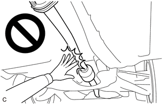
When the engine is hot, do not touch high-temperature areas such as the engine or exhaust pipe.
-
Touching high-temperature areas such as the engine and exhaust pipe could result in burns.
PROCEDURE
-
REMOVE FLYWHEEL HOUSING UNDER COVER
-
Remove the flywheel housing under cover from the stiffening crankcase assembly.
-
-
REMOVE DRIVE PLATE AND TORQUE CONVERTER ASSEMBLY SETTING BOLT
-
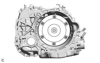
Turn the crankshaft to gain access to the 6 drive plate and torque converter assembly setting bolts and remove each drive plate and torque converter assembly setting bolt while holding the crankshaft pulley bolt with a wrench.
Tech Tips
There will be one black colored drive plate and torque converter assembly setting bolt.
-
-
REMOVE ENGINE ASSEMBLY WITH TRANSAXLE
-
INSTALL ENGINE HANGER
-
DISCONNECT ENGINE WIRE
-
Disconnect the transmission wire connector.
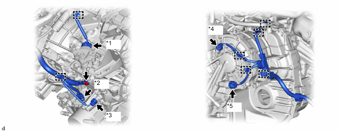
*1 Park/Neutral Position Switch Connector *2 Transmission Wire Connector *3 Transmission Revolution Sensor (NIN) Connector *4 Transmission Revolution Sensor (NOUT) Connector *5 Oil Pressure Sensor Connector - - -
Disconnect the transmission revolution sensor (NIN) connector.
-
Disconnect the park/neutral position switch connector.
-
Disconnect the transmission revolution sensor (NOUT) connector.
-
Disconnect the oil pressure sensor connector.
-
Disengage the 7 clamps to disconnect the engine wire from the continuously variable transaxle assembly.
-
Remove the bolt to disconnect the engine wire from the continuously variable transaxle assembly.
-
Disengage the 3 clamps to disconnect the engine wire from the front suspension crossmember sub-assembly.
-
-
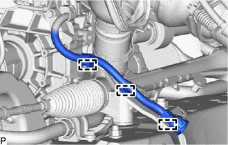
DISCONNECT WATER HOSE
-
Slide the 2 hose clips and disconnect the water hoses from the transmission oil cooler.
-
Disengage the 2 clamps to separate the water hose from the continuously variable transaxle assembly.
-
-
REMOVE STARTER ASSEMBLY (for Valeo Made Cold Area Specification Vehicles)
-
REMOVE STARTER ASSEMBLY (for Valeo Made except Cold Area Specification Vehicles)
-
REMOVE STARTER ASSEMBLY (for Denso Made without Stop and Start System)
-
REMOVE FLYWHEEL HOUSING SIDE COVER
-
REMOVE ENGINE ASSEMBLY
-
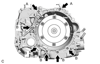
Remove the 7 bolts and engine assembly from the continuously variable transaxle assembly.
Note
To prevent damage to the 2 knock pins, do not pry between the continuously variable transaxle assembly and engine assembly.
Tech Tips
-
Bolt (A): Remove from continuously variable transaxle assembly side.
-
Bolt (B): Remove from engine assembly side.
-
-
-
REMOVE TORQUE CONVERTER ASSEMBLY
-
Remove the torque converter assembly from the continuously variable transaxle assembly.
Note
Remove the torque converter assembly from the input shaft horizontally.
-
-
REMOVE CVT OIL PUMP TYPE T OIL SEAL
Note
-
Do not remove the front oil pump assembly from the CVT main body, as there is a possibility of the entry of dust and foreign matter.
-
Clean the work area, the tools to be used, and other equipment, etc. thoroughly before the operation, as there is the possibility that a CVT malfunction, which could prevent the vehicle from being able to be driven, could occur if dust or fine foreign matter enters the CVT.
-
Do not use cotton work gloves, cloths, or paper towels, etc. that may produce lint, dust or foreign matter.
-
Perform the operation as quickly as possible, as dust and foreign matter could enter the CVT while the torque converter assembly is removed.
-
Do not use an air gun until the torque converter assembly has been installed, as it could cause dust and foreign matter to be stirred up.
-
Clean the tips of both the claws of SST and the center bolt.
- SST
- 09308-10010
-
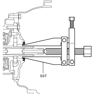
Using SST, remove the CVT oil pump type T oil seal.
Note
Pay attention to the angle of the claws when opening them, and ensure that they do not come into contact with the oil pump housing, as there is the possibility that metal particles could be produced if they do.
-
-
REMOVE TRANSFER ASSEMBLY
-
REMOVE TRANSFER AND TRANSAXLE SETTING STUD BOLT
-
REMOVE FRONT SUSPENSION CROSSMEMBER SUB-ASSEMBLY
-
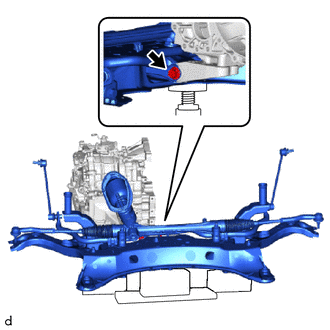
Remove the bolt and front suspension crossmember sub-assembly from the No. 2 engine moving control rod.
-
-
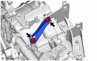
REMOVE NO. 2 ENGINE MOVING CONTROL ROD
-
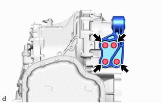
Remove the 4 bolts and No. 2 engine moving control rod from the continuously variable transaxle assembly.
-
-
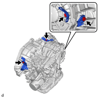
REMOVE ENGINE MOUNTING STAY LH
-
Remove the 2 bolts and engine mounting stay LH from the continuously variable transaxle assembly and transverse engine engine mounting bracket.
-
-
REMOVE TRANSVERSE ENGINE ENGINE MOUNTING BRACKET
-
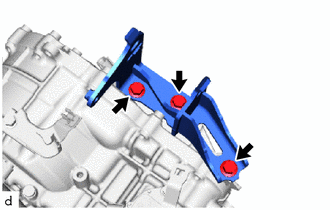
Remove the 3 bolts and transverse engine engine mounting bracket from the continuously variable transaxle assembly.
-
-
REMOVE WIRE HARNESS CLAMP BRACKET
-
Remove the 4 bolts and 4 wire harness clamp brackets from the continuously variable transaxle assembly.
-
-
REMOVE NO. 1 TRANSMISSION CONTROL CABLE BRACKET
-
Remove the 2 bolts and No. 1 transmission control cable bracket from the continuously variable transaxle assembly.
-
-
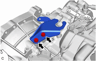
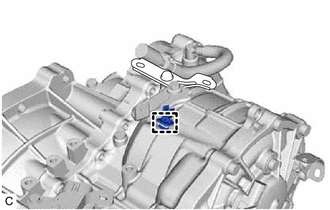
REMOVE NO. 1 HEATER BRACKET SUB-ASSEMBLY
-
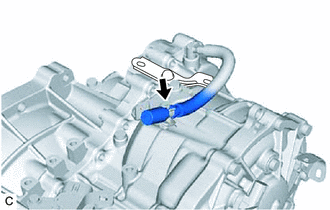
Separate the No. 1 breather plug (CVT) from the clamp.
-
Remove the clamp from the No. 1 heater bracket sub-assembly.
-
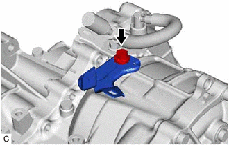
Remove the bolt and No. 1 heater bracket sub-assembly from the continuously variable transaxle assembly.
-
-
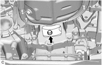
REMOVE STRAIGHT SCREW PLUG
Tech Tips
Perform this procedure only when replacement of the straight screw plug is necessary.
-
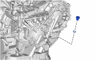
Remove the straight screw plug and gasket from the continuously variable transaxle assembly.
-
-
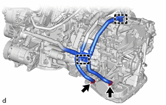
REMOVE TRANSMISSION BREATHER HOSE SUB-ASSEMBLY
Tech Tips
Perform this procedure only when replacement of the transmission breather hose sub-assembly is necessary.
-
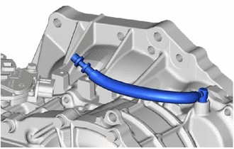
Remove the transmission breather hose sub-assembly from the continuously variable transaxle assembly.
-
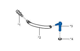
*1 No. 1 Breather Plug (CVT) *2 Breather Plug Hose *3 No. 2 Breather Plug (CVT) *4 O-ring Remove the No. 1 breather plug (CVT) and No. 2 breather plug (CVT) from the breather plug hose.
-
Remove the O-ring from the No. 2 breather plug (CVT).
-
-
INSPECT TORQUE CONVERTER ASSEMBLY
-
INSPECT DRIVE PLATE AND RING GEAR SUB-ASSEMBLY