EXHAUST PIPE INSTALLATION
PROCEDURE
INSTALL FRONT EXHAUST PIPE ASSEMBLY
-
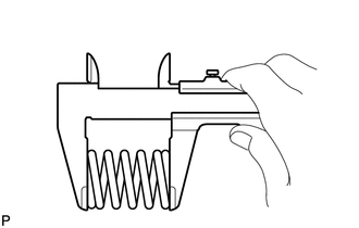
Using a vernier caliper, measure the free length of the compression springs.
Minimum free length
41.5 mm (1.63 in.)
If the free length is less than the minimum, replace the compression spring.
Using a wire brush, remove any foreign matter from the gasket installation surface.
-
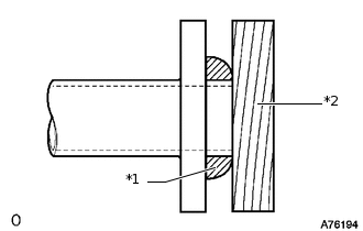
*1
Gasket
*2
Wooden Block
Using a plastic-faced hammer and wooden block, tap in a new gasket until its surface is flush with the exhaust manifold.
Note:Be sure to install the gasket so that it faces the correct direction.
Do not reuse the gasket.
Do not damage the gasket.
When connecting the front exhaust pipe assembly, do not push in the gasket with the front exhaust pipe assembly.
Install the front exhaust pipe assembly and 2 compression springs with the 2 bolts.
43 N*m
438 kgf*cm
32 ft.*lbf
-
INSTALL CENTER EXHAUST PIPE ASSEMBLY
Install a new gasket to the front exhaust pipe assembly.
Connect the 3 exhaust pipe supports to install the center exhaust pipe assembly.
Install the 2 bolts.
43 N*m
438 kgf*cm
32 ft.*lbf
INSTALL TAIL EXHAUST PIPE ASSEMBLY
-
Using a vernier caliper, measure the free length of the compression springs.
Minimum free length
38.5 mm (1.52 in.)
If the free length is less than the minimum, replace the compression spring.
-
*1
Gasket
*2
Wooden Block
Using a plastic-faced hammer and wooden block, tap in a new gasket until its surface is flush with the center exhaust pipe assembly.
Note:Be sure to install the gasket so that it faces the correct direction.
Do not reuse the gasket.
Do not damage the gasket.
When connecting the tail exhaust pipe assembly, do not push in the gasket with the tail exhaust pipe assembly.
Connect the 2 exhaust pipe supports to install the tail exhaust pipe assembly.
Install the 2 compression springs and 2 bolts.
43 N*m
438 kgf*cm
32 ft.*lbf
-
CONNECT HEATED OXYGEN SENSOR (for Bank 1 Sensor 2)
Note:Do not strike the metal part of the heated oxygen sensor.
Rotate the heated oxygen sensor counterclockwise the same number of times as recorded in the removal procedure, and then connect it to the center exhaust pipe assembly by hand.
Note:After rotating the heated oxygen sensor counterclockwise the same number of times as in the removal procedure, connect it while making sure that the wire harness is not twisted.
-
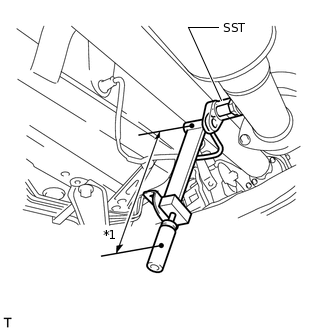
*1
Fulcrum Length
Using SST, tighten the heated oxygen sensor.
09224-00010
without SST
44 N*m
449 kgf*cm
32 ft.*lbf
with SST
40 N*m
408 kgf*cm
30 ft.*lbf
Tip:Use a torque wrench with a fulcrum length of 30 cm (11.8 in.). When using a torque wrench with a fulcrum length that is not 30 cm (11.8 in.), calculate the torque specification for the torque wrench and SST based on the "without SST" torque specification.
Make sure SST and the wrench are connected in a straight line.
Connect the grommet to the floor panel.
INSPECT FOR EXHAUST GAS LEAK
If gas is leaking, tighten the areas necessary to stop the leak. Replace damaged parts as necessary.
Tip:If an exhaust gas leak has been repaired, perform an inspection following the repair.