INTELLIGENT PARKING ASSIST SYSTEM SYSTEM DESCRIPTION
-
GENERAL
-
The parking assist ECU uses vehicle condition signals from the spiral cable with sensor sub-assembly, power steering ECU, skid control ECU, power management control ECU, etc. to make calculations and estimates. These results are used to make various guide lines, which are combined together with video from the rear television camera assembly, and output to the radio and display receiver assembly*1 or navigation receiver assembly*2. Also, control signals are output to each ECU and various intelligent parking assist system controls are performed.
-
This system has a rear television camera assembly mounted on the back door to display an image of the area behind the vehicle on the radio and display receiver assembly*1 or navigation receiver assembly*2 display. The display panel also shows a composite view consisting of the area behind the vehicle and parking guide lines to assist the driver in parking the vehicle by monitoring the area behind the vehicle.
-
This system is equipped with a self-diagnosis system, which is operated on a designated window that appears on the display panel, just as in the navigation system.
-
*1: for Radio and Display Type
-
*2: for Navigation Receiver Type
-
-
-
FUNCTION OF COMPONENTS
-
The parking assist ECU controls the system by using information from the following components.
Component Function Rear Television Camera Assembly
-
Mounted on the back door to transmit an image of the area behind the vehicle to the parking assist ECU.
-
Has a color video camera that uses a Complementary Metal Oxide Semiconductor (CMOS) and a wide-angle lens.
Parking Assist ECU Receives vehicle condition signals from various ECUs, makes frame based on calculations, combines the frame with video from the rear television camera assembly, and outputs the video with frame to the radio and display receiver assembly*1 or navigation receiver assembly*2. Also, control signals are output to each ECU and the intelligent parking assist system various controls are performed.
-
Radio and Display Receiver Assembly*1
-
Navigation Receiver Assembly*2
Receives video signals containing a composite of an image of the area behind the vehicle and the frame signals from the parking assist ECU, and displays them on the display panel. Spiral Cable with Sensor Sub-assembly Detects the angle of the steering wheel and sends the resulting signals to the parking assist ECU via CAN communication. Power Management Control ECU Sends the shift state signal (accelerator opening angle, front HV motor revolution angle) to the parking assist ECU via CAN communication. Brake Actuator (Skid Control ECU) Sends the stop switch signal, vehicle speed signal, driving distance signal, and other vehicle condition signals to the parking assist ECU. Power Steering ECU Assembly
-
Sends EPS failure, intervention steering, and other related vehicle condition signals to the parking assist ECU.
-
Performs steering control based on intelligent parking assist control signals and steering-related signals.
Parking Assist Pre Support Switch Assembly Sends the switch operation signal to the parking assist ECU. No. 1 Ultrasonic Sensor Controlled by the parking assist ECU and detects an available parking space. Air Conditioning Amplifier Assembly Sends the outside temperature signal to the parking assist ECU via CAN communication. Rear Height Control Sensor Sub-assembly RH Sends the vehicle height signal to the parking assist ECU. Main Body ECU (Multiplex Network Body ECU) Transmits a back door courtesy light switch signal to the parking assist ECU via CAN communication. -
-
*1: for Radio and Display Type
-
*2: for Navigation Receiver Type
-
-
OPERATION EXPLANATION
-
The parking assist ECU receives the rear television camera assembly activation information from the radio and display receiver assembly*1 or navigation receiver assembly*2. Then, the parking assist ECU switches the display signal for the radio and display receiver assembly*1 or navigation receiver assembly*2 from the navigation system to the intelligent parking assist system.
-
*1: for Radio and Display Type
-
*2: for Navigation Receiver Type
-
-
-
SWITCH OF INTELLIGENT PARKING ASSIST DISPLAY MODE
-
When either the navigation or information display is shown and the shift lever is moved to R with a shift state other than reverse (R) previously selected, the display switches to the intelligent parking assist display and the intelligent parking assist system on/off button is shown. Under this condition, the intelligent parking assist system display and guide line display are alternately selected each time the button is pressed.
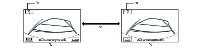
Text in Illustration *a Intelligent Parking Assist System On/Off Button *b Intelligent Parking Assist Display Mode *c Intelligent Parking Assist System On/Off Button Pressed *d Guide Line Mode Radio and Display Receiver Assembly*1 or Navigation Receiver Assembly*2 Displayed Screen Shift State Intelligent Parking Assist System On/Off Button
(Button Indicator)
Displayed Screen (Can be Switched by Pressing Intelligent Parking Assist System On/Off Button) Navigation Display or Information display Other than reverse (R) → reverse (R) On
(Illuminated)
Navigation display or information display → intelligent parking assist display (intelligent parking assist system On mode) Off
(Not illuminated)
Navigation display or information display → guide line mode display (intelligent parking assist system Off mode)
-
*1: for Radio and Display Type
-
*2: for Navigation Receiver Type
-
-
DISPLAY MODE SETTING
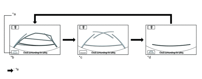
Text in Illustration *a Line Mode Button *b Estimated Guide Line Mode *c Parking Guide Line Mode *d Guide Line Deletion Mode *e Line Mode Button Pressed - -
-
While the guide line mode monitor is displayed, pressing the line mode button switches the guide line mode monitor display mode.
Guide Line Mode Monitor Display Mode Intelligent Parking Assist Display Mode Distance Guide Lines
(Red)
Estimated Course Lines
(Yellow)
Distance Guide Lines
(Yellow)
Vehicle Width Extension Guide Line
(Blue)
Distance Guide Line
(Blue)
Parking Assist Guide Lines
(Blue)
Estimated course line display mode Displayed Displayed Displayed Displayed Displayed Not displayed Parking Guide Line Mode Displayed Not displayed Not displayed Displayed Not displayed Displayed Distance guide line display mode Displayed Not displayed Not displayed Not displayed Not displayed Not displayed
-
-
PRE SUPPORT FUNCTION
-
Function Description
-
A pre support function is provided to assist the driver with initial positioning of the vehicle when backing-in mode or parallel parking mode operation is used.
-
-
Pre Support Function Operation Condition
-
For the pre support function, when the intelligent parking assist system is operating normally (no DTCs are stored) and the following conditions are met, pressing the parking assist pre support switch assembly changes the image displayed on the screen and pre support operation starts.
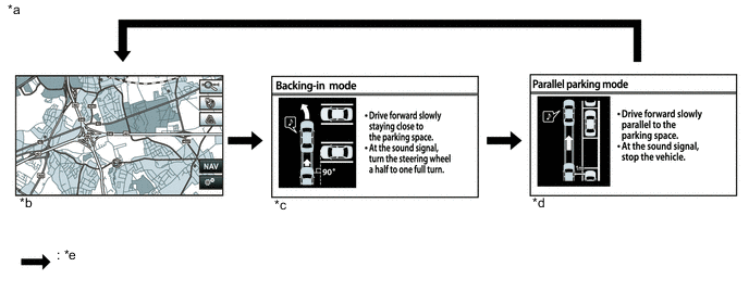
Text in Illustration *a Example *b Pre support function off (Audio screen, navigation screen*1 or information setting screen) *c Pre support function on (Parallel parking mode) *d Pre support function on (Backing-in mode) *e Parking assist pre support switch assembly is pressed. - -
-
*1: w/ Navigation System
Screen Displayed on Radio and Display Receiver Assembly*1 or Navigation Receiver Assembly*2 Shift State Vehicle Speed Screen Displayed
(Display switches in the following sequence when parking assist pre support switch assembly is pressed)*4
Audio screen, navigation screen*3 or information setting screen Other than Park (P) or reverse (R) 15 km/h (9.3 mph) or less Pre support off (Audio screen, navigation screen*3 or information setting screen) → Pre support on (Parallel parking mode) → Pre support on (Backing-in mode) → Pre support off (Audio screen, navigation screen*3 or information setting screen)*4
-
*1: for Radio and Display Type
-
*2: for Navigation Receiver Type
-
*3: w/ Navigation System
-
*4: A tone sounds when the screen transfers.
-
-
-
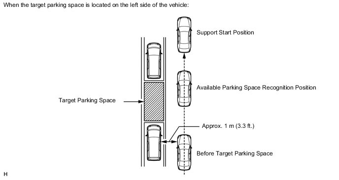
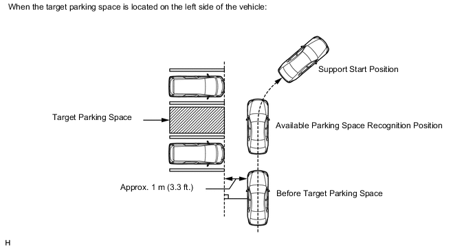
Parallel Parking Mode Operation
-
Press the parking assist pre support switch assembly before the target parking space to turn on the pre support function (parallel parking mode).
-
Drive the vehicle slowly while keeping a distance of approximately 1 m (3.3 ft.) from and parallel to the target parking space or vehicles around the target parking space to allow the ultrasonic sensor (No. 1 ultrasonic sensor) to start detection.
Tech Tips
-
For parallel parking mode, a tone will not sound when the ultrasonic sensor (No. 1 ultrasonic sensor) detects the available parking space.
-
An available parking space may not be detected by the ultrasonic sensor (No. 1 ultrasonic sensor) depending on the distance between the vehicle being parked and the target parking space or vehicles around the target parking space, vehicle orientation and vehicle speed.
-
A target parking space may not be detected by the ultrasonic sensor (No. 1 ultrasonic sensor) depending on the conditions around the target parking space. For details, refer to Precautions for the parking space detection sensor Click here.
-
-
Drive as is and stop the vehicle when the vehicle reaches the support start position (the tone will sound twice), and move the shift lever to R.
Tech Tips
When the ultrasonic sensor (No. 1 ultrasonic sensor) cannot detect a target parking space, the tone will not sound.
-
When the intelligent parking assist screen is displayed, the target parking frame will also be displayed for the target parking space that is detected by the ultrasonic sensor (No. 1 ultrasonic sensor) during the pre support function operation.
-
-
Backing-in Mode Operation
-
Press the parking assist pre support switch assembly before the target parking space to turn on the pre support function (backing-in mode).
-
Drive the vehicle slowly while keeping a distance of approximately 1 m (3.3 ft.) from and perpendicular to the target parking space or vehicles around the target parking space. When the ultrasonic sensor (No. 1 ultrasonic sensor) detects an available parking space, start to turn the steering wheel from the straight ahead position when the tone sounds.
Tech Tips
-
An available parking space may not be detected by the ultrasonic sensor (No. 1 ultrasonic sensor) depending on the distance between the vehicle being parked and the target parking space or vehicles around the target parking space, vehicle orientation and vehicle speed.
-
A target parking space may not be detected by the ultrasonic sensor (No. 1 ultrasonic sensor) depending on the conditions around the target parking space. For details, refer to Precautions for the parking space detection sensor Click here.
-
When the ultrasonic sensor (No. 1 ultrasonic sensor) cannot detect a target parking space, a tone will not sound.
-
-
Drive the vehicle while turning the steering wheel and when the vehicle reaches the support start position (the tone will sound twice), stop the vehicle, return the steering wheel to the straight ahead position, and move the shift lever to R.
-
When the intelligent parking assist screen is displayed, the target parking frame will also be displayed for the target parking space that is detected by the ultrasonic sensor (No. 1 ultrasonic sensor) during the pre support function operation.
-
-
-
EASY SET FUNCTION (ONLY WHEN PARKING)
Tech Tips
-
Under the following conditions, the easy set function may not operate because parking lines (white) cannot be recognized:
-
Parking spaces without parking lines (parking spaces marked with rope, blocks etc.)
-
Unclear, dirty or chipped parking lines
-
Parking spaces with lines that are difficult to differentiate from the road surface due to a small brightness difference (such as yellow lines on concrete)
-
Under the following conditions, the easy set function may misrecognize a target parking space:
-
Parking spaces with interfering lines or objects (lines other than parking lines or obstacles such as poles)
-
Parking spaces on a slope
-
If detection of the space is affected by nearby vehicles (such as the shadow, grill or side step of a nearby vehicle)
-
Unclear, dirty or chipped parking lines
-
Parking spaces with lines that are difficult to differentiate from the road surface due to a small brightness difference (such as yellow lines on concrete)
-
Move the shift lever to R
Tech Tips
-
Intelligent parking assist system ON/OFF button is on.
-
Parking assist pre support switch assembly has not been pressed.
-
-
A short sound is emitted when the system recognizes a parking space. After this, when OK on the navigation screen is selected, the system starts parking assist.
-
-
COMMUNICATION SYSTEM OUTLINE
-
The components of the intelligent parking assist system communicate with each other via AVC-LAN communication.
-
If a short circuit or open circuit occurs in the AVC-LAN, communication is interrupted and this system will stop functioning.
-
-
DIAGNOSTIC FUNCTION OUTLINE
-
This intelligent parking assist system has a diagnostic function displayed on the radio and display receiver assembly*1 or navigation receiver assembly*2. This function enables the calibration (adjustment and verification) of the intelligent parking assist system Click here.
-
The following items for the intelligent parking assist system can be checked using the GTS.
Item Proceed to DTC Data List / Active Test
-
*1: for Radio and Display Type
-
*2: for Navigation Receiver Type
-