СИСТЕМА SFI, Diagnostic DTC:P0420, P0430
| DTC Code | DTC Name |
|---|---|
| P0420 | Catalyst System Efficiency Below Threshold (Bank 1) |
| P0430 | Catalyst System Efficiency Below Threshold (Bank 2) |
DESCRIPTION
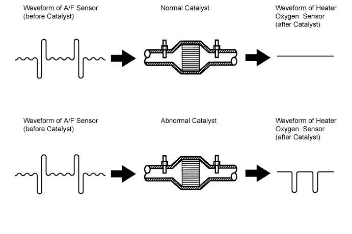
The ECM observes the waveform of the heated oxygen sensor located behind the catalyst to determine whether the catalyst performance has deteriorated.
If the catalyst is functioning normally, the waveform of the heated oxygen sensor located behind the catalyst switches back and forth between rich and lean much more slowly.
When the waveform of the heated oxygen sensor located behind the catalyst alternates frequently between rich and lean, it indicates that catalyst performance has deteriorated.
| DTC No. | DTC Detection Condition | Trouble Area |
|---|---|---|
| P0420 | After engine and catalyst are warmed up, and while vehicle is driven within set vehicle and engine speed range, waveform of heated oxygen sensor (bank 1 sensor 2) alternates frequently between rich and lean (2 trip detection logic) |
|
| P0430 | After engine and catalyst are warmed up, and while vehicle is driven within set vehicle and engine speed range, waveform of heated oxygen sensor (bank 2 sensor 2) alternates frequently between rich and lean (2 trip detection logic) |
|
CONFIRMATION DRIVING PATTERN
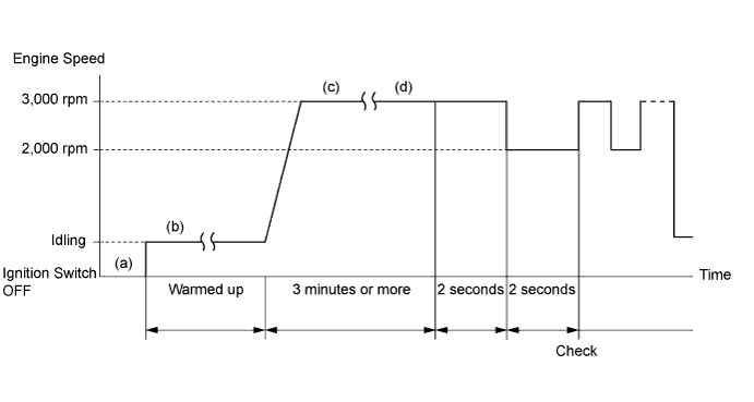
(a) Connect the intelligent tester to the DLC3.
(b) Start the engine and warm it up with all the accessories switched OFF until the water temperature is stable.
(c) Race the engine at 2,500 to 3,000 rpm for about 3 minutes.
(d) When racing the engine at 3,000 rpm for 2 seconds and 2,000 rpm for 2 seconds alternately, check the waveform of the heated oxygen sensor (sensor 2).
INSPECTION PROCEDURE
Tech Tips
-
Read freeze frame data using the intelligent tester. Freeze frame data records the engine conditions when a malfunction is detected. When troubleshooting, freeze frame data can help determine if the vehicle was running or stopped, if the engine was warmed up or not, if the air-fuel ratio was lean or rich, and other data from the time the malfunction occurred.
-
Bank 1 refers to the bank that includes the No. 1 cylinder.
-
Bank 2 refers to the bank that does not include the No. 1 cylinder.
-
Sensor 1 refers to the sensor closest to the engine assembly.
-
Sensor 2 refers to the sensor farthest away from the engine assembly.
PROCEDURE
-
CHECK OTHER DTC OUTPUT (BESIDES DTC P0420 AND/OR P0430)
-
Connect the intelligent tester to the DLC3.
-
Turn the ignition switch ON and the tester ON.
-
Enter the following menus: Powertrain / Engine and ECT / DTC.
-
Read the DTCs.
Result Display (DTC output) Proceed to Only P0420 and/or P0430 are output A P0420 or P0430 and other DTCs are output B Tech Tips
If any other codes besides P0420 and/or P0430 are output, perform troubleshooting for those DTCs first.
B 
GO TO RELEVANT DTC CHART
A 
-
-
CHECK FOR EXHAUST GAS LEAKAGE
NG
REPAIR OR REPLACE EXHAUST GAS LEAKAGE POINT
OK
-
INSPECT AIR FUEL RATIO SENSOR (BANK 1, 2 SENSOR 1)
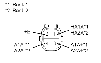
-
Disconnect the A/F sensor connector.
-
Measure the resistance of the A/F sensor.
Standard resistance (Bank 1 Sensor 1) Tester Connection Condition Specified Condition 1 (HA1A) - 2 (+B) 20°C (68°F) 1.8 to 3.4 Ω 1 (HA1A) - 4 (A1A-) - 10 kΩ or higher Standard resistance (Bank 2 Sensor 1) Tester Connection Condition Specified Condition 1 (HA2A) - 2 (+B) 20°C (68°F) 1.8 to 3.4 Ω 1 (HA2A) - 4 (A2A-) - 10 kΩ or higher
NG
REPLACE AIR FUEL RATIO SENSOR
OK
-
-
INSPECT HEATED OXYGEN SENSOR (BANK 1, 2 SENSOR 2)
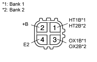
-
Disconnect the heated oxygen sensor connector.
-
Measure the resistance of the sensor.
Standard resistance (Bank 1 Sensor 2) Tester Connection Condition Specified Condition 1 (HT1B) - 2 (+B) 20°C (68°F) 5 to 10 Ω 1 (HT1B) - 4 (E2) - 10 kΩ or higher Standard resistance (Bank 2 Sensor 2) Tester Connection Condition Specified Condition 1 (HT2B) - 2 (+B) 20°C (68°F) 5 to 10 Ω 1 (HT2B) - 4 (E2) - 10 kΩ or higher
NG
REPLACE HEATED OXYGEN SENSOR
OK 
REPLACE THREE-WAY CATALYTIC CONVERTER
-