MONITOR SYSTEM DETAILS
-
FUNCTION OF MAIN COMPONENTS
Component Function Rear Television Camera Assembly Transmits a video signal representing the area behind the vehicle to the radio and display receiver assembly*1 or display and navigation module display*2. Radio and Display Receiver Assembly*1
-
Receives signals from the park/neutral position switch assembly and turns the rear television camera assembly on and off.*3
-
Receives signals from the back-up light switch assembly and turns the rear television camera assembly on and off.*4
-
Displays the image transmitted by the rear television camera assembly on the screen.
Display and Navigation Module Display*2 Park/Neutral Position Switch Assembly*3 Sends a shift R position signal to the radio and display receiver assembly*1 or display and navigation module display*2. Back-up Light Switch Assembly*4 Transmits the on/off signal of the back-up light switch assembly to the radio and display receive assembly*1 or the display and navigation module display*2.
-
*1: Models with display audio system
-
*2: Models with navigation system
-
*3: Models with automatic transmission
-
*4: Models with manual transmission
-
-
OPERATING CONDITION
-
This system operates when both the following conditions have been met:
-
The ignition switch is ON.
-
The shift lever is moved to R.*1
-
The back-up light switch is on.*2
-
*1: Models with automatic transmission
-
*2: Models with manual transmission
-
-
-
FUNCTION
-
Area Displayed on Screen
-
Objects on the right of the vehicle appear on the right side of the display panel, and objects on the left of the vehicle appear on the left side of the display panel.
-
The rear television camera assembly uses a wide-angle lens. The perceived distance from images that appear on the screen differs from the actual distance.
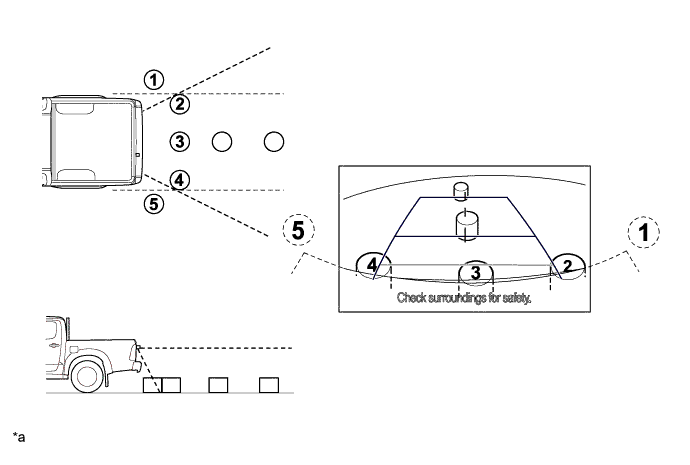
Text in Illustration *a The illustrations shown are examples only. The illustrations may differ from the actual vehicle screens. - - Tech Tips
-
The area displayed on the screen may vary in accordance with vehicle status or road conditions.
-
The area covered by the rear television camera assembly is limited. The rear television camera assembly does not show objects close to either corner of the bumper or show the area under the bumper.
-
-
-
Warning Message
-
A warning message appears at the bottom of the screen under the following conditions.
Message Appearing at Bottom of Screen Warning Message Condition Check surroundings for safety. This message always appears during system operation.
-
-
-
CONSTRUCTION
-
Rear Television Camera Assembly
-
The rear television camera assembly consists of a wide-angle lens and a Complementary Metal Oxide Semiconductor (CMOS).
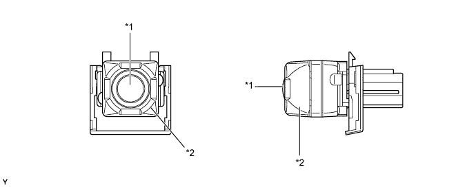
Text in Illustration *1 Wide-angle Lens *2 Rear Television Camera Assembly
-
-
-
FAIL-SAFE
-
The table below indicates fail-safe operation when a malfunction is detected:
Malfunctioning Part Detection Item Function Rear Television Camera Assembly Rear television camera assembly malfunction signal is detected. System stops signal reception and displays a dark screen.
-