ECD SYSTEM(for Swirl Control Valve), Diagnostic DTC:P1410
| DTC Code | DTC Name |
|---|---|
| P1410 | Enhanced SRC Check for the Adapted Diesel Particulate Filter Differential Pressure Too High |
DESCRIPTION
Refer to DTC P0471 (Click here).
DTC No. |
DTC Detection Condition |
Trouble Area |
|---|---|---|
P1410 |
Differential pressure sensor value exceeds upper limit for 1.5 seconds. (3 trip detection logic) |
|
DTC No. |
Data List |
|---|---|
P1410 |
Adaptation Value of Differential Pressure at Particle Filter |
WIRING DIAGRAM
Refer to DTC P0471 (Click here).
CAUTION / NOTICE / HINT
When replacing the ECM, the ECM needs Registration and Initialization (Click here).
After replacing the differential pressure sensor, the ECM needs initialization (Click here).
When the ECM must be replaced, before replacing the ECM, perform the "Learning Values Save" function using the GTS. Then after installing the new ECM, perform all of the initialization/registrations for the "Learning Values Write" function by following the instructions shown on the GTS display.
Read freeze frame data using the GTS. Freeze frame data records the engine condition when malfunctions are detected. When troubleshooting, freeze frame data can help determine if the vehicle was moving or stationary, if the engine was warmed up or not, and other data from the time the malfunction occurred.
PROCEDURE
CHECK HARNESS AND CONNECTOR (DIFFERENTIAL PRESSURE SENSOR - ECM)
Disconnect the differential pressure sensor connector.
Disconnect the ECM connector.
Measure the resistance according to the value(s) in the table below.
Standard Resistance
Tester Connection
Condition
Specified Condition
C115-1 (VC) - C112-70 (VCPX)
Always
Below 1 Ω
C115-2 (PEX) - C112-85 (PEX)
Always
Below 1 Ω
C115-3 (E2) - C112-71 (EPEX)
Always
Below 1 Ω
C115-1 (VC) or C112-70 (VCPX) - Body ground
Always
10 kΩ or higher
C115-2 (PEX) or C112-85 (PEX) - Body ground
Always
10 kΩ or higher
C115-3 (E2) or C112-71 (EPEX) - Body ground
Always
10 kΩ or higher
REPAIR OR REPLACE HARNESS OR CONNECTORClick here
CHECK HARNESS AND CONNECTOR (VC VOLTAGE)
Disconnect the differential pressure sensor connector.
Measure the voltage according to the value(s) in the table below.
Standard Voltage
Tester Connection
Switch Condition
Specified Condition
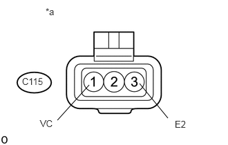
C115-1 (VC) - C115-3 (E2)
Ignition switch ON
4.5 to 5.5 V
Table 2. Text in Illustration *a
Front view of wire harness connector
(to differential pressure sensor)
REPLACE ECMClick here
CHECK DIFFERENTIAL PRESSURE SENSOR AIR HOSE CONNECTION
Check the hose pipe from the exhaust emission system to the differential pressure sensor (for correct installation, sooting and leaks).
OK
Part is securely installed.
REPAIR AIR HOSEClick here
READ VALUE USING GTS (ADAPTATION VALUE OF DIFFERENTIAL PRESSURE AT PARTICLE FILTER)
Note:The EGR valve is closed during the test.
Connect the GTS to the DLC3.
Turn the ignition switch to ON and turn the GTS on.
Enter the following menus: Powertrain / Engine and ECT / Data List / Adaptation Value of Differential Pressure at Particle Filter.
Start the engine and warm it up until the engine coolant temperature is 80°C (176°F) or higher.
Test 1
Idle the engine for 2 seconds.
Read the value for 10 seconds.
OK
With the ignition switch ON, "Adaptation Value of Differential Pressure at Particle Filter" value is within 3.5 kPa.
Test 2
Maintain the engine speed at 2000 rpm for 2 seconds.
Maintain the engine speed at 2000 rpm and read the value for 10 seconds.
OK
With the ignition switch ON, "Adaptation Value of Differential Pressure at Particle Filter" value is within 7.5 kPa.
Test 3
With the engine running without load at approximately 3800 rpm, wait for 2 seconds.
With the engine running without load at approximately 3800 rpm, read the value for 10 seconds.
OK
With the ignition switch ON, "Adaptation Value of Differential Pressure at Particle Filter" value is within 20 kPa.
CONFIRM WHETHER MALFUNCTION HAS BEEN SUCCESSFULLY REPAIREDClick here
REPLACE DIFFERENTIAL PRESSURE SENSORClick here
REPAIR OR REPLACE HARNESS OR CONNECTOR
Repair or replace the harness or connector.
CONFIRM WHETHER MALFUNCTION HAS BEEN SUCCESSFULLY REPAIREDClick here
REPLACE ECM
Replace the ECM (Click here).
CONFIRM WHETHER MALFUNCTION HAS BEEN SUCCESSFULLY REPAIREDClick here
REPAIR AIR HOSE
Install the air hose.
CONFIRM WHETHER MALFUNCTION HAS BEEN SUCCESSFULLY REPAIREDClick here
REPLACE DIFFERENTIAL PRESSURE SENSOR
Replace the differential pressure sensor (Click here).
Perform the differential pressure learning value reset (Click here).
CONFIRM WHETHER MALFUNCTION HAS BEEN SUCCESSFULLY REPAIRED
Connect the GTS to the DLC3.
Turn the ignition switch to ON and turn the GTS on.
Clear the DTCs (Click here).
Turn the ignition switch off and wait for 60 seconds or more [A].
Perform road test [B].
Repeat [A] and [B] for the number of trips detected.
Enter the following menus: Powertrain / Engine and ECT / Trouble Codes.
Confirm that the DTC is not output again.
END