CONTINUOUSLY VARIABLE TRANSAXLE SYSTEM TERMINALS OF ECM
ECM
 Tip:
Tip:The standard voltage and resistance of each ECM terminal is shown in the table below.
In the table, first follow the information under "Condition". Look under "Terminal No. (Symbol)" for the terminals to be inspected. The standard voltage or resistance between the terminals is shown under "Specified Condition".
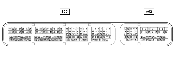
Use the illustration above as a reference for the ECM terminals.
Terminal No. (Symbol)
Wiring Color
Terminal Description
Condition
Specified Condition
A62-1 (BATT) - B93-59 (E1)
W - BR
Battery (for measuring battery voltage and for ECM memory)
Always
11 to 14 V
A62-2 (+B) - B93-59 (E1)
R - BR
Power source of ECM
Ignition switch ON
11 to 14 V
A62-3 (+B2) - B93-59 (E1)
P - BR
Power source of ECM
Ignition switch ON
11 to 14 V
A62-9 (STP) - B93-59 (E1)
L - BR
Stop light switch assembly signal
Brake pedal depressed
7.5 to 14 V
Brake pedal released
Below 1.5 V
A62-13 (CANH) - B93-59 (E1)
Y - BR
CAN communication line
Ignition switch ON
Pulse generation
A62-23 (NSW) - B93-59 (E1)
W - BR
Park/neutral position switch signal
Ignition switch ON and shift lever in P or N
Below 1 V
Ignition switch ON and shift lever not in P or N
11 to 14 V
A62-26 (CANL) - B93-59 (E1)
W - BR
CAN communication line
Ignition switch ON
Pulse generation
A62-42 (SFTU) - B93-59 (E1)
LG - BR
Up-shift position switch signal
Ignition switch ON and shift lever in M
11 to 14 V
Ignition switch ON and shift lever in "+"
Ignition switch ON and "+" shift paddle switch operated*
Below 1 V
A62-43 (SFTD) - B93-59 (E1)
Y - BR
Down-shift position switch signal
Ignition switch ON and shift lever in M
11 to 14 V
Ignition switch ON and shift lever in "-"
Ignition switch ON and "-" shift paddle switch operated*
Below 1 V
A62-46 (MREL) - B93-59 (E1)
P - BR
EFI-MAIN NO. 1 relay
Ignition switch ON
11 to 14 V
A62-59 (S) - B93-59 (E1)
L - BR
M position switch signal
Ignition switch ON and shift lever in M, "+" or "-"
11 to 14 V
Ignition switch ON and shift lever not in M, "+" or "-"
Below 1 V
B93-29 (+BM) - B93-59 (E1)
L - BR
Power source of ECM
Always
11 to 14 V
B93-39 (SLP+) - B93-38 (SLP-)
P - V
Shift solenoid valve SLP signal
Engine idling
Pulse generation
B93-41 (SC) - B93-59 (E1)
GR - BR
Shift solenoid valve SC signal
For 1 second after moving shift lever from P to D or R, or N to D or R
Lock-up ON to OFF
Pulse generation
B93-43 (SLU+) - B93-42 (SLU-)
W - B
Shift solenoid valve SLU signal
Lock-up turned from OFF to ON
Pulse generation
B93-45 (SLS+) - B93-44 (SLS-)
Y - L
Shift solenoid valve SLS signal
Engine idling
Pulse generation
B93-59 (E1) - Body ground
BR - Body ground
Ground
Always
Below 1 Ω
B93-64 (R) - B93-59 (E1)
R - BR
R position switch signal
Ignition switch ON and shift lever in R
11 to 14 V
Ignition switch ON and shift lever not in R
Below 1 V
B93-65 (D) - B93-59 (E1)
B - BR
D position switch signal
Ignition switch ON and shift lever in D, M, "+" or "-"
11 to 14 V
Ignition switch ON and shift lever not in D, M, "+" or "-"
Below 1 V
B93-67 (SL) - B93-59 (E1)
L - BR
Shift solenoid valve SL signal
Lock-up operating
Pulse generation
B93-69 (N) - B93-59 (E1)
Y - BR
N position switch signal
Ignition switch ON and shift lever in N
11 to 14 V
Ignition switch ON and shift lever not in N
Below 1 V
B93-70 (P) - B93-59 (E1)
L - BR
P position switch signal
Ignition switch ON and shift lever in P
11 to 14 V
Ignition switch ON and shift lever not in P
Below 1 V
B93-79 (PTO) - B93-109 (EPTO)
B - W
Oil pressure sensor signal
Engine idling with shift lever in P
0.8 to 1.2 V
B93-110 (VCPT) - B93-109 (EPTO)
R - W
Power supply for oil pressure sensor
Ignition switch ON
4.5 to 5.5 V
B93-125 (NTO) - B93-59 (E1)
L - BR
Transmission revolution sensor (NT) signal
When driving with shift lever in D
Pulse generation
B93-126 (NTB) - B93-59 (E1)
W - BR
Power supply for transmission revolution sensor (NT)
Ignition switch ON
11 to 14 V
B93-123 (NIN+) - B93-124 (NIN-)
W - B
Transmission revolution sensor (NIN) signal
When driving with shift lever in D
Pulse generation
B93-127 (NOTO) - B93-59 (E1)
W - BR
Transmission revolution sensor (NOUT) signal
When driving with shift lever in D
Pulse generation
B93-128 (NOTB) - B93-59 (E1)
R - BR
Power supply for transmission revolution sensor (NOUT)
Ignition switch ON
11 to 14 V
B93-129 (THO1) - B93-130 (ETHO)
LG - BR
CVT fluid temperature sensor signal
CVT fluid temperature: 60 to 120°C (140 to 248°F)
0.2 to 1.0 V
*: w/ Shift Paddle Switch