WIPER AND WASHER SYSTEM TERMINALS OF ECU
CHECK WINDSHIELD WIPER RELAY ASSEMBLY (w/Auto Wiper System)

Disconnect the E95 windshield wiper relay assembly connector.
Measure the voltage and resistance on the wire harness side connector according to the value(s) in the table below.
Terminal No.
(Symbol)
Wiring Color
Terminal Description
Condition
Specified Condition
E95-2 (IG) - Body ground
L - Body ground
Ignition switch ON signal (Power source circuit)
Ignition switch ON
11 to 14 V
Ignition switch off
Below 1 V
E95-8 (VR2) - E95-21(VR1)
B - P
Adjusting volume circuit
Windshield wiper switch adjusting ring* changed
0 to 231 Ω
E95-12 (E) - Body ground
BR - Body ground
Body ground
Always
Below 1 Ω
E95-16 (WIG) - Body ground
B - Body ground
Signal power source circuit
Ignition switch ON
11 to 14 V
Ignition switch off
Below 1 V
E95-25 (W) - Body ground
W - Body ground
Front washer switch circuit
Front washer switch on
Below 1 Ω
Front washer switch off
10 kΩ or higher
Tip:*: The rain sensor sensitivity can be adjusted by the windshield wiper switch adjusting ring.
If the result is not as specified, there may be a malfunction in the wire harness.
Reconnect the E95 windshield wiper relay assembly connector.
Measure the voltage and check for pulses according to the value(s) in the table below.
Terminal No.
(Symbol)
Wiring Color
Terminal Description
Condition
Specified Condition
E95-1 (+SM) - Body ground
G - Body ground
Front wiper motor position detection signal
Front wiper motor in low or high operation
Below 1 V ←→ 11 to 14V
Front wiper motor off
Below 1 V
E95-3 (C1) - E95-5 (C0)
L - R
Front wiper switch AUTO signal circuit
Ignition switch ON, front wiper switch in AUTO
Below 1 V
Ignition switch ON, front wiper switch off
11 to 14 V
E95-4 (W) - Body ground
W - Body ground
Front washer switch circuit
Ignition switch ON, front washer switch on
Below 1 V
Ignition switch ON, front washer switch off
11 to 14 V
E95-10 (+1) - Body ground
G - Body ground
Front wiper motor low speed signal circuit
Front wiper motor in low operation
11 to 14 V
Front wiper motor off
Below 1 Ω
E95-11 (+2) - Body ground
R - Body ground
Front wiper motor high speed signal circuit
Front wiper motor in high operation
11 to 14 V
Front wiper motor off
Below 1 V
E95-14 (MPX1) - Body ground
GR - Body ground
Rain sensor signal
Ignition switch ON
Pulse generation
E95-24 (SPD) - Body ground
V - Body ground
Speed signal
Ignition switch ON, wheel being rotated
Pulse generation
(See waveform 1)
Tip:If the result is not as specified, the windshield wiper relay assembly may have a malfunction.
-
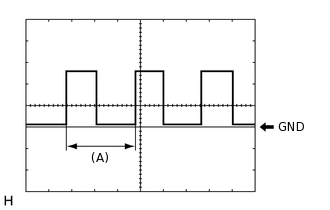
Waveform 1 (Reference):
Item
Condition
Tool setting
5 V/DIV., 20 ms./DIV.
Vehicle condition
Wheel being rotated
Tip:When the system is functioning normally, one wheel revolution generates 4 pulses. As the vehicle speed increases, the width indicated by (A) in the illustration narrows.
CHECK HEADLIGHT CLEANER CONTROL RELAY

Disconnect the A94 headlight cleaner control relay connector.
Measure the voltage and resistance on the wire harness side connector according to the value(s) in the table below.
Terminal No.
(Symbol)
Wiring Color
Terminal Description
Condition
Specified Condition
A94-3 (IG) - A94-4 (E)
L - W-B
Ignition switch ON signal (Power source circuit)
Ignition switch ON
11 to 14 V
Ignition switch off
Below 1 V
A94-4 (E) - Body ground
W-B - Body ground
Body ground
Always
Below 1 Ω
A94-5 (FRWA) - A94-4 (E)
W - W-B
Front washer switch signal
Ignition switch ON, front washer switch on
11 to 14 V
Ignition switch ON, front washer switch on
Below 1 V
A94-6 (PB) - A94-4 (E)
W - W-B
Headlight clear motor operation signal
Ignition switch off
11 to 14 V
Tip:If the result is not as specified, there may be a malfunction in the wire harness.
CHECK INSTRUMENT PANEL JUNCTION BLOCK ASSEMBLY AND MAIN BODY ECU (MULTIPLEX NETWORK BODY ECU)
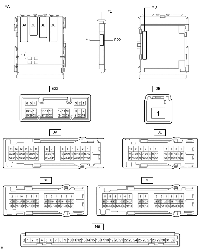
*A
Main Body ECU (Multiplex Network Body ECU) with 1 Connector
-
-
*1
Main Body ECU (Multiplex Network Body ECU)
-
-
*a
1 connector
-
-
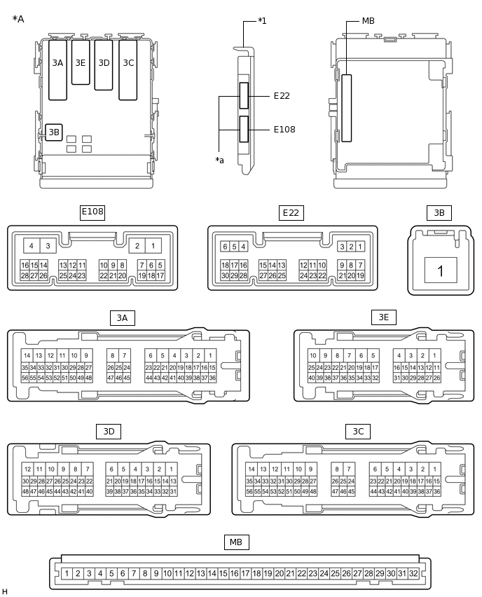
*A
Main Body ECU (Multiplex Network Body ECU) with 2 Connectors
-
-
*1
Main Body ECU (Multiplex Network Body ECU)
-
-
*a
2 connectors
-
-
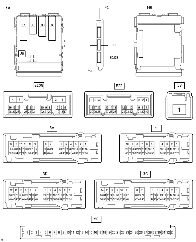
*A
Main Body ECU (Multiplex Network Body ECU) with 3 Connectors
-
-
*1
Main Body ECU (Multiplex Network Body ECU)
-
-
*a
3 connectors
-
-
Measure the voltage according to the value(s) in the table below.
Terminal No. (Symbol)
Wiring Color
Terminal Description
Condition
Specified Condition
3A-35 - Body ground
V - Body ground
Low beam headlight signal
Light control switch in head position
Below 1 V
Light control switch off
4.2 V or higher
If the result is not as specified, the main body ECU (multiplex network body ECU) or instrument panel junction block assembly may be malfunctioning.