LIGHTING SYSTEM TERMINALS OF ECU
CHECK COMBINATION METER ASSEMBLY
Measure the voltage and resistance according to the value(s) in the table below.
Terminal No. (Symbol)
Wiring Color
Terminal Description
Condition
Specified Condition
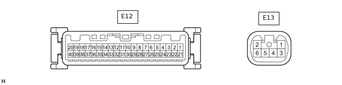
E12-7 (PANL) - Body ground
LG - Body ground
Interior lights power supply
DOME CUT relay off
Below 1 V
DOME CUT relay on
11 to 14 V
E12-9 (ACC) - Body ground
GR - Body ground
ACC power supply
Ignition switch off
Below 1 V
Ignition switch ACC
11 to 14 V
E12-38 (ET) - Body ground
W-B - Body ground
Ground
Always
Below 1 Ω
E12-39 (IG+) - Body ground
P - Body ground
IG power supply
Ignition switch off
Below 1 V
Ignition switch ON
11 to 14 V
E12-40 (B) - Body ground
L - Body ground
Battery
Always
11 to 14 V
E13-1 (DCTY) - Body ground
P - Body ground
Driver door courtesy light switch input
Driver door open
Below 1 V
Driver door closed
11 to 14 V
E13-2 (PCTY) - Body ground
L - Body ground
Door courtesy light switch (except driver door) input
Any door (except driver door) open
Below 1 V
Any door (except driver door) closed
11 to 14 V
E13-6 (OSPT) - Body ground
P - Body ground
Interior lights drive output
DOME CUT relay on, map light switch DOOR position and door open
Below 1 V
DOME CUT relay on, map light switch DOOR position and door closed
11 to 14 V
CHECK CERTIFICATION ECU (SMART KEY ECU ASSEMBLY) (w/ Entry and Start System)
Measure the voltage according to the value(s) in the table below.
Terminal No. (Symbol)
Wiring Color
Terminal Description
Condition
Specified Condition
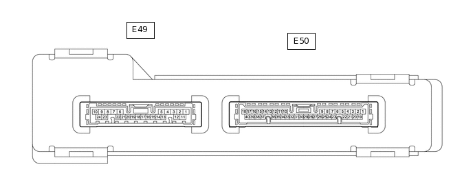
E49-19 (SWIL) - E49-24 (AGND)
R - B
Engine switch illumination drive output
Engine switch illumination on
9 to 14 V
Engine switch illumination off
Below 1 V