FUEL INJECTOR INSTALLATION
PROCEDURE
INSTALL INJECTOR VIBRATION INSULATOR
Install 3 new injector vibration insulators to the cylinder head sub-assembly.
INSTALL FUEL INJECTOR ASSEMBLY
-
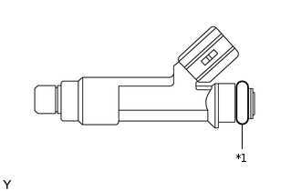
*1
O-ring
Apply a light coat of gasoline or spindle oil to new O-rings, and then install one onto each fuel injector assembly.
Apply a light coat of gasoline or spindle oil where the fuel delivery pipe contacts each O-ring.
-
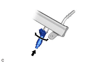
While turning the fuel injector assembly left and right, install it onto the fuel delivery pipe.
Note:Do not damage the fuel injector assembly or O-ring.
Do not twist the O-ring.
After installing each fuel injector assembly, check that it turns smoothly. If not, replace the O-ring with a new one.
Tip:Use the same procedure to install the other fuel injector assemblies.
-
INSTALL FUEL PIPE INSULATOR
Install the 2 fuel pipe insulators to the fuel delivery pipe.
INSTALL FUEL DELIVERY PIPE
-
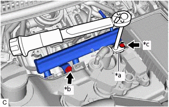
*a
12 mm Union Nut Wrench
*b
Bolt (A)
*c
Bolt (B)
Temporarily install the fuel delivery pipe with the 3 fuel injector assemblies and 2 fuel pipe insulators with the 2 bolts.
Note:Do not drop the fuel injector assemblies when installing the fuel delivery pipe.
After installing the fuel delivery pipe, check that the fuel injector assemblies turn smoothly.
Tighten the bolt (A).
27 N*m
275 kgf*cm
20 ft.*lbf
Using a 12 mm union nut wrench, tighten the bolt (B).
27 N*m
275 kgf*cm
20 ft.*lbf
Note:Use the torque value compensation formula to calculate the torque value for use when a torque wrench is combined with a tool such as a union nut wrench.
-
CONNECT FUEL TUBE SUB-ASSEMBLY
Note:Check if there is any damage or foreign matter on the connecting parts of the fuel lines.
-
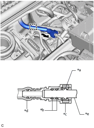
*a
Retainer
*b
O-ring
*c
Fuel Tube Connector
*d
Nylon Tube
*e
Fuel Pipe

Push
Connect the fuel tube sub-assembly to the fuel delivery pipe.
Align the fuel tube connector with the fuel pipe, and push them together until the fuel tube connector makes a "click" sound. If it is difficult to push the fuel pipe into the fuel tube connector, apply a small amount of clean engine oil to the tip of the fuel pipe and reinsert it.
After connecting the fuel lines, check that the fuel pipe and fuel tube connector are securely connected by pulling on them.
Engage the clamp to connect the fuel tube sub-assembly to the fuel hose clamp.
Install the No. 2 fuel pipe clamp to the fuel tube sub-assembly.
-
INSTALL WIRE HARNESS CLAMP BRACKET
Install the wire harness clamp bracket to the intake manifold with the bolt.
8.4 N*m
86 kgf*cm
74 in.*lbf
CONNECT ENGINE WIRE
Connect the 3 fuel injector assembly connectors.
Engage the 7 clamps.
Connect the 3 ignition coil assembly connectors, throttle body with motor assembly connector, EGR valve assembly connector and camshaft position sensor connector.
Connect the water by-pass hose assembly to the throttle body with motor assembly and slide the clip to secure it.
INSTALL AIR CLEANER CAP SUB-ASSEMBLY
ADD ENGINE COOLANT
CONNECT CABLE TO NEGATIVE BATTERY TERMINAL
Note:When disconnecting the cable, some systems need to be initialized after the cable is reconnected.
INSPECT FOR COOLANT LEAK
INSPECT FOR FUEL LEAK