БЛОК ДВИГАТЕЛЯ УСТАНОВКА

PROCEDURE
-
INSTALL IGNITION COIL ASSEMBLY
-
INSTALL SENSOR WIRE
-
Install the sensor wire to the cylinder block sub-assembly with the bolt.
- Torque:
- 21 N*m { 214 kgf*cm, 15 ft.*lbf }
-
Connect the knock control sensor connector.
-
-
INSTALL FUEL DELIVERY PIPE
-
INSTALL INTAKE MANIFOLD
-
INSTALL WATER INLET HOUSING
-
Using an E6 "TORX" socket wrench, install the 4 stud bolts to the water inlet housing.
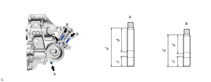
*a 34 mm (1.34 in.) *b 21 mm (0.827 in.) *c 9.0 mm (0.354 in.) *d 27 mm (1.06 in.) *e 16 mm (0.630 in.) - - - Torque:
- 4.4 N*m { 45 kgf*cm, 39 in.*lbf }
Note
If a stud bolt is deformed or its threads are damaged, replace it.
-
Install a new gasket to the cylinder block sub-assembly.
-
Install the water inlet housing to the cylinder block sub-assembly with the 4 bolts and nut.
- Torque:
- 43 N*m { 438 kgf*cm, 32 ft.*lbf }
-
-
INSTALL THERMOSTAT
-
INSTALL WATER INLET
-
INSTALL ENGINE WATER PUMP ASSEMBLY
-
INSTALL NO. 1 WATER BY-PASS PIPE
-
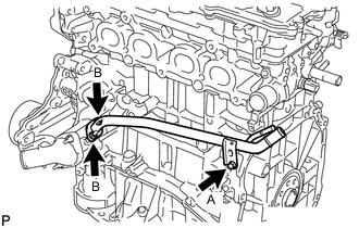
Install a new gasket and the No. 1 water by-pass pipe with the 2 nuts and bolt.
- Torque:
- 12 N*m { 122 kgf*cm, 9 ft.*lbf }
Note
Temporarily tighten the bolt (A), fully tighten the 2 nuts (B), and then fully tighten the bolt (A).
-
-
INSTALL WATER BY-PASS HOSE
-
Install the water by-pass hose to the cylinder head sub-assembly and slide the clip to secure it.
-
-
INSTALL NO. 2 WATER BY-PASS HOSE
-
Install the No. 2 water by-pass hose to the No. 1 water by-pass pipe and slide the clip to secure it.
-
-
INSTALL THROTTLE BODY GASKET
-
INSTALL THROTTLE BODY WITH MOTOR ASSEMBLY
-
INSTALL EXHAUST MANIFOLD CONVERTER SUB-ASSEMBLY (TWC: Front Catalyst)
-
INSTALL MANIFOLD STAY
-
INSTALL NO. 2 MANIFOLD STAY
-
INSTALL NO. 1 EXHAUST MANIFOLD HEAT INSULATOR
-
INSTALL V-RIBBED BELT TENSIONER ASSEMBLY
-
Type A:
-
Install the V-ribbed belt tensioner assembly to the water inlet housing with the bolt.
- Torque:
- 21 N*m { 214 kgf*cm, 15 ft.*lbf }
-
-
Type B:
-
Install the V-ribbed belt tensioner assembly to the water inlet housing with the bolt.
- Torque:
- 21 N*m { 214 kgf*cm, 15 ft.*lbf }
-
Install the dust cover to the V-ribbed belt tensioner assembly.
-
-
-
INSTALL ENGINE OIL LEVEL DIPSTICK GUIDE
-
Apply a light coat of engine oil to a new O-ring.
-
Install the O-ring to the engine oil level dipstick guide.
-
Install the engine oil level dipstick guide to the water inlet housing with the bolt.
- Torque:
- 10 N*m { 102 kgf*cm, 7 ft.*lbf }
-
Install the engine oil level dipstick.
-
-
INSTALL NO. 1 COMPRESSOR MOUNTING BRACKET
-
Install the No. 1 compressor mounting bracket with the 4 bolts.
- Torque:
- 21 N*m { 214 kgf*cm, 15 ft.*lbf }
-
-
INSTALL COMPRESSOR ASSEMBLY WITH PULLEY
-
INSTALL DRIVE SHAFT BEARING BRACKET
-
Install the drive shaft bearing bracket with the 3 bolts.
- Torque:
- 63.7 N*m { 650 kgf*cm, 47 ft.*lbf }
Note
Make sure that the bolts and bolt holes are free of oil. Clean them if necessary.
-