AIR CONDITIONING SYSTEM(for Automatic Air Conditioning System) TERMINALS OF ECU
-
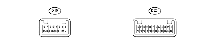
AIR CONDITIONING CONTROL ASSEMBLY
Tech Tips
Check from the rear of the connector while it is connected to the air conditioning control assembly.
Terminal No.
(Symbol)
Wiring Color Description Condition Specified Condition D19-1 (ACC) - D19-16 (GND) R-B - B-Y Power source (ACC) Ignition switch : OFF Below 1 V Ignition switch : ACC 10 to 16 V D19-2 (PSW) - D20-6 (SG) Y-B - LG A/C pressure switch signal Engine running
A/C system operating
Refrigerant pressure: Normal
10 to 16 V Engine running
A/C system operating
Refrigerant pressure: Abnormal
Below 1 V D20-6 (SG) - Body ground B-Y - Body ground Ground for sensor and servo motor Always Below 1 Ω D19-8 (HR) - D19-16 (GND) V-Y - B-Y Heater relay control signal Blower switch : OFF
Refrigerant, pressure: Normal
Below 1 V Blower switch : ON
Refrigerant, pressure: Normal
10 to 16 V D19-9 (+B) - D19-16 (GND) L-R - B-Y Power source (Back up) Always 10 to 16 V D19-10 (IG) - D19-16 (GND) G - B-Y Power source (IG) Ignition switch : OFF Below 1 V Ignition switch : IG 10 to 16 V D19-11 (ILL+) - D19-16 (GND) V - B-Y Tail indication light signal Headlight switch : OFF Below 1 V Headlight switch : TAIL 10 to 16 V D19-12 (CANL) - D19-16 (GND) L-Y - B-Y CAN communication circuit Ignition switch : ON Pulse generation D19-13 (CANH) - D19-16 (GND) L-W - B-Y CAN communication circuit Ignition switch : ON Pulse generation D19-14 (BLW) - D19-16 (GND) G-W - B-Y Blower motor speed control signal Ignition switch : ON
Blower switch : ON
Pulse generation
(See waveform 1)
D20-2 (CLTS) - Body ground Y - Body ground A/C solar sensor signal Ignition switch : ON
Solar sensor is subjected to electric light.
0.8 to 4.3 V D20-13 (S5) - D19-16 (GND) W - B-Y Power supply for sensor and servo motor Ignition switch : ON 4.75 to 5.25 V -
COMBINATION METER

Terminal No.
(Symbol)
Wiring Color Description Condition Specified Condition D7-24(TAM) - D7-25(SG-) L - W Ambient temperature sensor signal Ignition switch : ON
Ambient temperature at 25°C(77°F)
1.4 to 1.6 V D7-6(CANL) - Body ground BR - Body ground CAN communication circuit Ignition switch : ON Pulse generation D7-7(CANH) - Body ground BR-W - Body ground CAN communication circuit Ignition switch : ON Pulse generation -
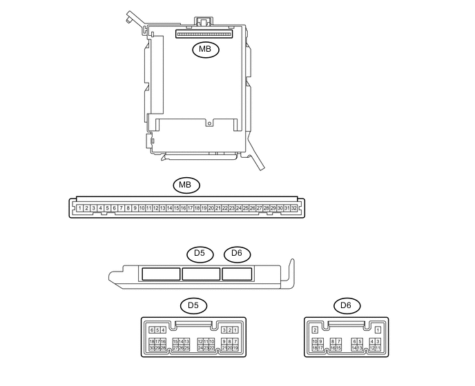
INSTRUMENT PANEL JUNCTION BLOCK ASSEMBLY, MAIN BODY ECU (NETWORK GATEWAY ECU)
-
Remove the main body ECU (network gateway ECU) from the instrument panel junction block assembly.
-
Measure the values on the wire harness side with the connector disconnected.
CONNECTOR MB Terminal No.
(Symbol)
Wiring Color Description Condition Specified Condition MB8(IG) - Body ground - Power source (IG) Ignition switch : ON 11 to 14 V MB9(ACC) - Body ground - Power source (ACC) Ignition switch : ACC 11 to 14 V MB11(GND) - Body ground - Ground for main power supply Always Below 1 Ω If the result is not as specified, there may be a malfunction in the wire harness.
-
Install the main body ECU (network gateway ECU) to the instrument panel junction block assembly.
-
Measure the voltage and resistance according to the value(s) in the table below.
Tech Tips
Measure the values on the wire harness side with the connector disconnected.
MAIN BODY ECU (NETWORK GATEWAY ECU) D5 Terminal No.
(Symbol)
Wiring Color Description Condition Specified Condition D5-13(CANL) - D5-14(CANH) LG - P CAN communication circuit Ignition switch : ON Pulse generation D6-13(CLTE) - Body ground G - Body ground Ground for solar sensor Always Below 1 Ω D6-15(CLTB) - Body ground R - Body ground Power supply for solar sensor Ignition switch : ON 4.75 to 5.25 V
-
-
ECM
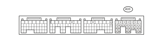
Terminal No.
(Symbol)
Wiring Color Description Condition Specified Condition A33-8(ACP) - Body ground G - Body ground Air conditioner pressure switch signal Engine running
A/C system operating
Refrigerant pressure: Abnormal
Below 1 V Engine running
A/C system operating
Refrigerant pressure: Normal
10 to 16 V A33-18(CANL) - A33-19(CANH) B-P - O CAN communication circuit Ignition switch : ON Pulse generation