MANUAL TRANSAXLE UNIT REASSEMBLY
PROCEDURE
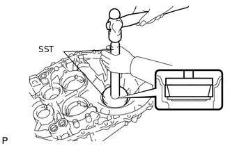
INSTALL SHIFT FORK SHAFT BEARING
-
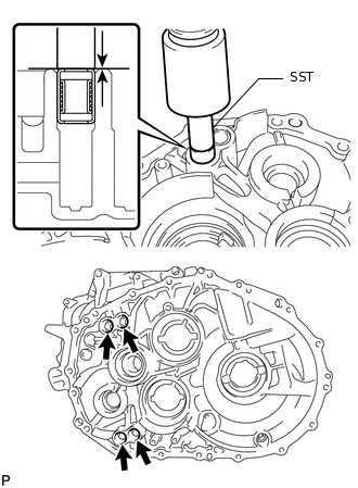
Using SST and a press, press in 4 new shift fork shaft bearings.
09820-00031
Standard depth
0 to 0.5 mm (0 to 0.0196 in.)
-
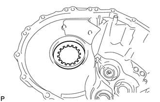
INSTALL OUTPUT SHAFT COVER
-
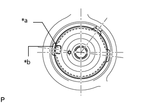
*a
Protrusion
*b
Groove
Install the output shaft cover as shown in the illustration.
-
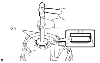
INSTALL FRONT NO. 2 OUTPUT SHAFT BEARING OUTER RACE
-
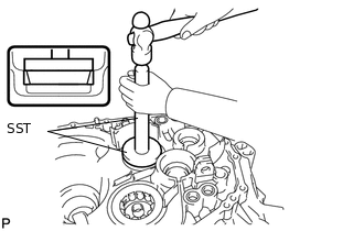
Using SST and a hammer, tap in the front No. 2 output shaft bearing outer race.
09950-60020
09951-00720
09950-70010
09951-07100
-
INSTALL OUTPUT SHAFT COVER
-
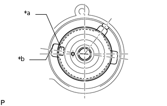
*a
Protrusion
*b
Groove
Install the output shaft cover as shown in the illustration.
-
INSTALL FRONT OUTPUT SHAFT BEARING
-
Using SST and a press, install a new front output shaft bearing to the front transaxle case.
09223-15020
-
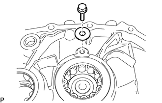
Install the bearing lock plate with the bolt.
11.3 N*m
115 kgf*cm
8 ft.*lbf
Coat a front output shaft bearing with gear oil.
-
INSTALL TRANSAXLE CASE OIL SEAL
-
Using SST and a hammer, install a new transaxle case oil seal to the front transaxle case.
09950-60010
09951-00420
Standard depth
4.4 to 5.0 mm (0.174 to 0.196 in.)
Coat the lip of the transaxle case oil seal with MP grease.
-
INSTALL FRONT INPUT SHAFT BEARING
-
Using SST and a press, install a new front input shaft bearing to the front transaxle case.
09223-00010
-
Install the bearing lock plate with the bolt.
11.3 N*m
115 kgf*cm
8 ft.*lbf
Coat the front input shaft bearing with gear oil.
-
INSTALL REAR INPUT AND OUTPUT SHAFT BEARING SHAFT SNAP RING
-
Using a snap ring expander, install the rear input and output shaft bearing shaft snap rings.
-
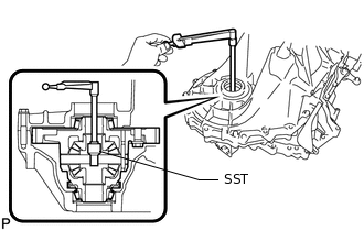
INSTALL SHIFT AND SELECT LEVER SHAFT NEEDLE ROLLER BEARING
-
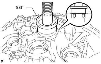
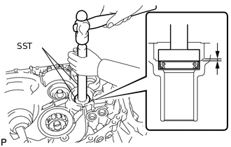
Using SST and a press, press in a new shift and select lever shaft needle roller bearing.
09285-76010
Clearance
177.8 to 178.7 mm (7.00 to 7.03 in.)
-
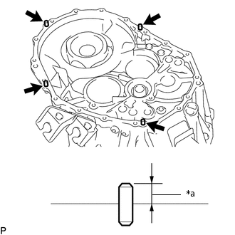
INSTALL SHIFT FORK SHAFT BEARING
-
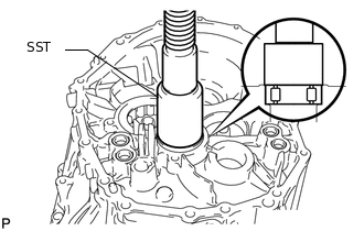
Using SST and a press, press in 4 new shift fork shaft bearings to the manual transmission case.
09307-12010
09820-00031
Clearance A
168.2 to 169.3 mm (6.63 to 6.66 in.)
Clearance B
162.2 to 163.3 mm (6.39 to 6.42 in.)
-
INSTALL FRONT DIFFERENTIAL CASE FRONT TAPERED ROLLER BEARING
-
Using SST and a hammer, tap in the front differential case front tapered roller bearing.
09950-70010
09951-07150
09951-00900
-
INSTALL FRONT DIFFERENTIAL CASE REAR OUTER RACE BEARING
-
Install the front differential case rear shim into the manual transmission case.
-
Using SST and a hammer, install the front differential case rear outer race bearing.
09950-70010
09951-07100
09951-00900
-
INSTALL MANUAL TRANSMISSION CASE STRAIGHT PIN
*a
Protrusion
Using a plastic-faced hammer, tap in the 4 new manual transmission case straight pins to the front transaxle case.
Protrusion height
10.5 to 11.5 mm (0.414 to 0.452 in.)
ADJUST DIFFERENTIAL SIDE BEARING PRELOAD
-
Coat the front differential case assembly with gear oil and install it to the front transaxle case.
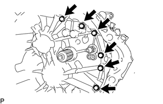
-
Install the manual transmission case to the front transaxle case with the 12 bolts.
29.4 N*m
300 kgf*cm
22 ft.*lbf
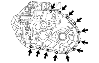
-
Install the 6 bolts to the front transaxle case side.
29.4 N*m
300 kgf*cm
22 ft.*lbf
Turn the differential case in both directions and make sure it turns smoothly.
-
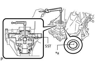
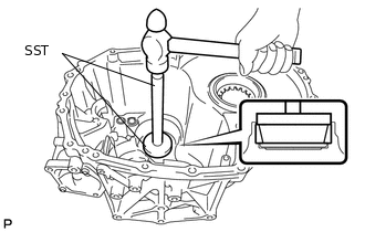
*a
Mark
Using SST and a torque wrench, measure the starting preload.
09564-33010
Standard Preload (at starting)
1.0 to 2.49 N*m (11 to 25 kgf*cm, 9 to 22 in.*lbf)
If the preload is not as specified, replace the front differential case rear shim with one of a different thickness. Use the table below to select a front differential case rear shim which will ensure that the preload is within the specification.
Standard Shim Thickness
Mark
Specified Condition
Mark
Specified Condition
0
2.00 mm (0.0787 in.)
9
2.45 mm (0.0965 in.)
1
2.05 mm (0.0807 in.)
A
2.50 mm (0.0984 in.)
2
2.10 mm (0.0827 in.)
B
2.55 mm (0.1004 in.)
3
2.15 mm (0.0846 in.)
C
2.60 mm (0.1024 in.)
4
2.20 mm (0.0866 in.)
D
2.65 mm (0.1043 in.)
5
2.25 mm (0.0886 in.)
E
2.70 mm (0.1063 in.)
6
2.30 mm (0.0906 in.)
F
2.75 mm (0.1083 in.)
7
2.35 mm (0.0925 in.)
G
2.80 mm (0.1102 in.)
8
2.40 mm (0.0945 in.)
H
2.85 mm (0.1122 in.)
Remove the 18 bolts and manual transmission case.
-
INSTALL REAR NO. 2 OUTPUT SHAFT BEARING OUTER RACE
-
*a
Mark
Install the rear output shaft bearing shim to the manual transmission case.
Tip:When reusing the output shaft rear tapered roller bearing, first install a shim of the same thickness as the original. When installing a new output shaft front bearing, first select and install a rear output shaft bearing shim which is thinner than the original.
-
Using SST and a hammer, install the rear No. 2 output shaft bearing outer race.
09950-60010
09951-00650
09950-70010
09951-07200
-
ADJUST REAR NO. 2 OUTPUT SHAFT BEARING PRELOAD
-
Install the No. 2 output shaft assembly and front differential case assembly to the front transaxle case.
-
Install the manual transmission case to the front transaxle case with the 12 bolts.
29.4 N*m
300 kgf*cm
22 ft.*lbf
-
Install the 6 bolts to the front transaxle case side.
29.4 N*m
300 kgf*cm
22 ft.*lbf
-
Using SST and a torque wrench, measure the rear No. 2 output shaft bearing preload. Subtract the value of the differential side bearing preload from the measured rear No. 2 output shaft bearing preload.
09564-33010
Standard Preload (at starting)
4.14 to 5.87 N*m (43 to 59 kgf*cm, 37 to 51 in.*lbf)
If the preload is not as specified, replace the shim with one of a different thickness. Use the table below to select a shim which will ensure that the preload is within the specification.
Bearing Shim Thickness
Mark
Specified Condition
Mark
Specified Condition
A
1.80 mm (0.0709 in.)
K
2.25 mm (0.0886 in.)
B
1.85 mm (0.0728 in.)
L
2.30 mm (0.0906 in.)
C
1.90 mm (0.0748 in.)
M
2.35 mm (0.0925 in.)
D
1.95 mm (0.0768 in.)
N
2.40 mm (0.0945 in.)
E
2.00 mm (0.0787 in.)
P
2.45 mm (0.0965 in.)
F
2.05 mm (0.0807 in.)
Q
2.50 mm (0.0984 in.)
G
2.10 mm (0.0827 in.)
R
2.55 mm (0.1004 in.)
H
2.15 mm (0.0846 in.)
S
2.60 mm (0.1024 in.)
J
2.20 mm (0.0866 in.)
T
2.65 mm (0.1043 in.)
Remove the 18 bolts and manual transmission case.
Remove the No. 2 output shaft assembly from the front transaxle case.
Remove the front differential assembly case from the front transaxle case.
-
INSTALL TRANSMISSION MAGNET
-
Clean and install the transmission magnet to the front transaxle case.
-
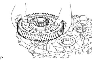
INSTALL FRONT DIFFERENTIAL CASE ASSEMBLY
-
Coat the front differential case assembly with gear oil, and install it to the front transaxle case.
-
INSTALL TRANSMISSION OIL SEPARATOR
-
for Front Transaxle Case Side:
Install the transmission oil separator to the front transaxle case with the 2 bolts.
8.5 N*m
87 kgf*cm
75 in.*lbf
-
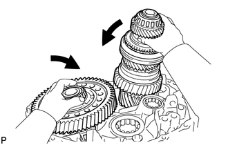
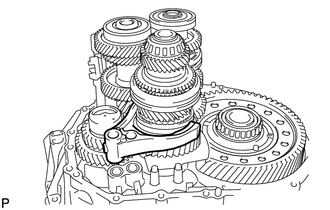
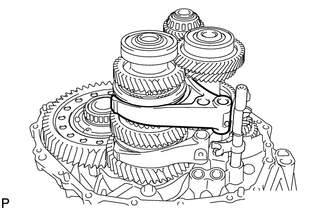
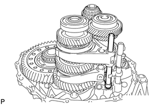
INSTALL INPUT SHAFT, NO. 1 OUTPUT SHAFT ASSEMBLY AND NO. 2 OUTPUT SHAFT ASSEMBLY
-
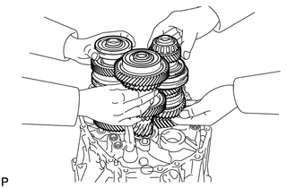
Install the 3 shafts at the same time.
-
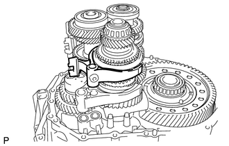
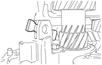
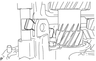
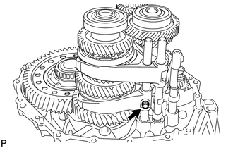
INSTALL REVERSE IDLER GEAR
-
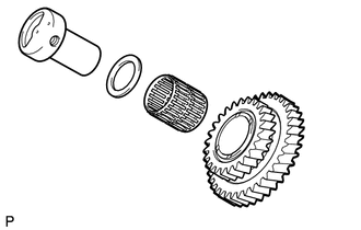
Coat the reverse idler gear, needle roller bearing and reverse idler thrust washer with MP grease, and install them to the reverse idler gear shaft.
Tip:Make sure that the protruding part of the reverse idler thrust washer fits into the groove of the reverse idler shaft.
-
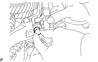
Install the reverse idler gear shaft by sliding and lifting it.
-
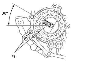
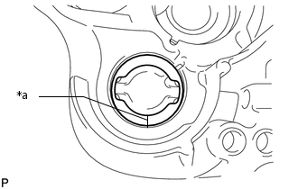
*a
Align the Mark
Align the mark of the reverse idler gear shaft with the hole of the bolt.
-
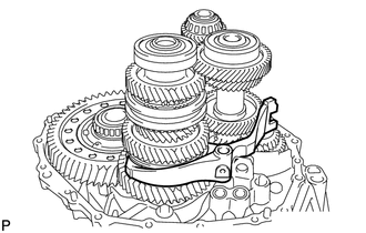
INSTALL REVERSE SHIFT FORK
-
Install the reverse shift fork to the No. 2 output shaft assembly.
-
INSTALL NO. 3 GEAR SHIFT FORK
-
Install the No. 3 gear shift fork to the No. 2 output shaft assembly.
-
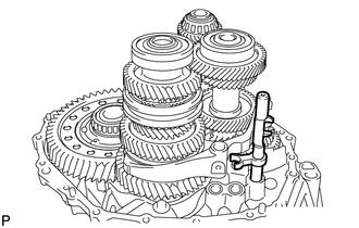
INSTALL 5TH AND 6TH SHIFT FORK SHAFT
-
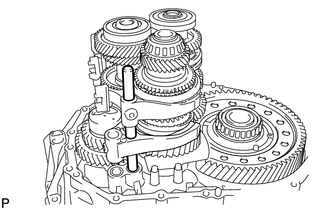
Install the 5th and 6th shift fork shaft to the front transaxle case.
Coat the threads of the bolt with adhesive.
Adhesive
Toyota Genuine Adhesive 1344, Three Bond 1344 or equivalent
-
Install the bolt to the No. 3 gear shift fork.
19.6 N*m
200 kgf*cm
14 ft.*lbf
-
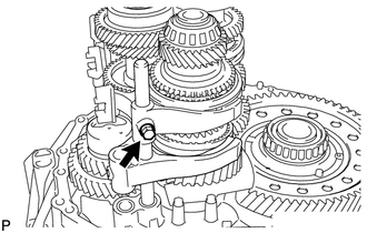
INSTALL REVERSE SHIFT FORK SHAFT
-
Install the reverse shift fork shaft to the front transaxle case.
Coat the threads of the bolt with adhesive.
Adhesive
Toyota Genuine Adhesive 1344, Three Bond 1344 or equivalent
-
Install the bolt to the reverse gear shift fork.
19.6 N*m
200 kgf*cm
14 ft.*lbf
-
INSTALL SHIFT ARM
-
Install the shift arm to the front transaxle case.
-
INSTALL NO. 1 GEAR SHIFT FORK
-
Install the No. 1 gear shift fork to the No. 1 output shaft assembly.
-
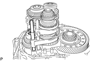
INSTALL NO. 5 GEAR SHIFT FORK SHAFT
-
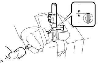
Install the No. 3 gear shift head to the No. 5 gear shift fork shaft.
Using a 5 mm pin punch and hammer, tap a new pin into the No. 3 gear shift head.
Standard depth
-0.5 to 0.5 mm (-0.0197 to 0.0196 in.)
-
Install the No. 5 gear shift fork shaft to the front transaxle case.
-
Connect the shift arm to the No. 5 gear shift fork shaft.
-
Install the pin to the shift arm.
-
Using a brass bar and hammer, tap a new E-ring to the pin.
-
INSTALL NO. 2 GEAR SHIFT FORK
-
Install the No. 2 gear shift fork to the No. 1 output shaft assembly.
-
INSTALL 3RD AND 4TH SHIFT FORK SHAFT
-
Install the No. 2 gear shift head to the 3rd and 4th shift fork shaft.
Install the 3rd and 4th shift fork shaft to the front transaxle case.
-
Using a 5 mm pin punch and hammer, tap a new pin into the No. 2 gear shift fork.
Standard depth
-0.5 to 0.5 mm (-0.0197 to 0.0196 in.)
-
Using a 5 mm pin punch and hammer, tap a new pin into the No. 2 gear shift head.
Standard depth
-0.5 to 0.5 mm (-0.0197 to 0.0196 in.)
-
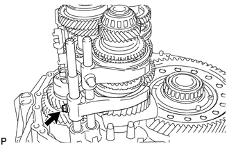
INSTALL 1ST AND 2ND SHIFT FORK SHAFT
-
Install the 1st and 2nd shift fork shaft to the front transaxle case.
Coat the threads of the bolt with adhesive.
Adhesive
Toyota Genuine Adhesive 1344, Three Bond 1344 or equivalent
-
Install the bolt to the No. 1 gear shift fork.
19.6 N*m
200 kgf*cm
14 ft.*lbf
-
INSTALL TRANSMISSION OIL SEPARATOR
-
for Manual Transmission Case Side:
Install the transmission oil separator to the manual transmission case with the 2 bolts.
8.5 N*m
87 kgf*cm
75 in.*lbf
-
INSTALL NO. 1 OIL RECEIVER PIPE
-
Install the No. 1 oil receiver pipe to the manual transmission case.
Note:Do not damage the No. 1 oil receiver pipe.
-
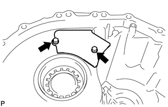
INSTALL MANUAL TRANSMISSION CASE
Clean the contact surface of the manual transmission case and front transaxle case with non-residue solvent.
-
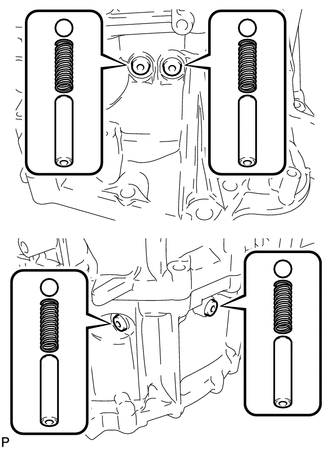
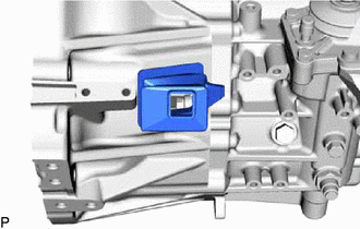
*a
Seal Packing
Apply seal packing to the manual transmission case as shown in the illustration.
Seal packing
Toyota Genuine Seal Packing 1281, Three Bond 1281 or equivalent
Seal diameter
1.2 mm (0.0472 in.)
Note:Assemble parts within 10 minutes of application. Otherwise, the seal packing must be removed and reapplied.
-
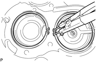
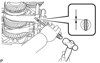
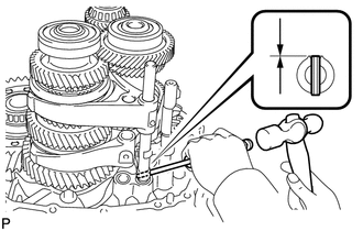
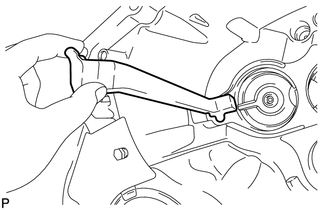
Using 2 pairs of snap ring pliers to keep the snap ring stretched, install the manual transmission case.
-
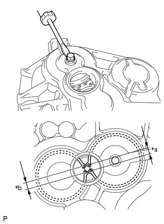
*a
8.5 mm (0.3346 in.)
*b
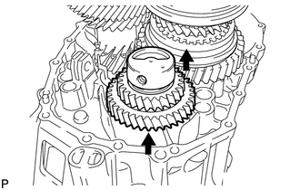
9.3 mm (0.3661 in.)
Install a bolt to the No. 1 output shaft assembly and lift the No. 1 output shaft assembly from the service hole. Make sure that the output shaft rear bearing shaft snap ring and input shaft bearing shaft snap ring are positioned correctly in the bearing grooves by checking that the distances between the centers of snap ring holes are as shown in the illustration.
-
Install the manual transmission case to the front transaxle case with the 12 bolts.
29.4 N*m
300 kgf*cm
22 ft.*lbf
-
Install the 6 bolts to the front transaxle case.
29.4 N*m
300 kgf*cm
22 ft.*lbf
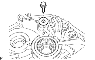
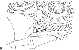
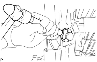
INSTALL REVERSE IDLER GEAR SHAFT BOLT
-
Coat the reverse idler gear shaft bolt with adhesive, and install a new gasket and the shaft bolt.
Adhesive
Toyota Genuine Adhesive 1344, Three Bond 1344 or equivalent
80 N*m
816 kgf*cm
59 ft.*lbf
-
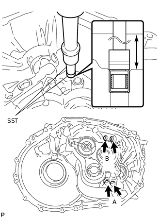
INSTALL SHIFT DETENT BALL
Clean the threads of the 4 detent ball plugs.
-
Apply a few drops of adhesive to 2 or 3 threads of each of the 4 detent ball plugs.
Adhesive
Toyota Genuine Adhesive 1344, Three Bond 1344 or equivalent
Using a 6 mm hexagon wrench, install the 4 shift detent balls, 4 shift detent ball compression springs, 4 No. 1 shift ball spring seats and 4 detent ball plugs.
22.4 N*m
228 kgf*cm
17 ft.*lbf
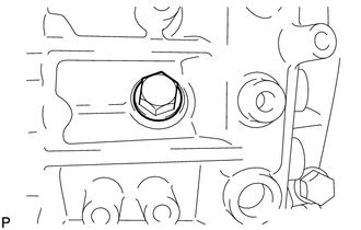
INSTALL MANUAL TRANSMISSION CASE PLUG
Clean the contact surface of the manual transmission case and manual transmission case plug.
-
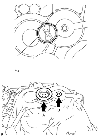
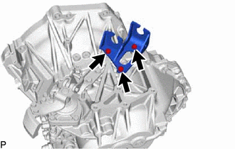
*a
Seal Packing
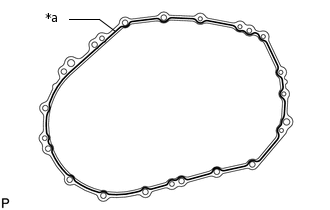
Apply seal packing to the manual transmission case as shown in the illustration.
Seal packing
Toyota Genuine Seal Packing 1281, Three Bond 1281 or equivalent
Apply a few drop of the adhesive to 2 or 3 threads of the 2 manual transmission case plugs.
Adhesive
Toyota Genuine Adhesive 1344, Three Bond 1344 or equivalent
Install the 2 manual transmission case plugs to the manual transmission case.
for manual transmission case plug A
55 N*m
561 kgf*cm
41 ft.*lbf
for manual transmission case plug B
22.4 N*m
228 kgf*cm
17 ft.*lbf
INSTALL O-RING
-
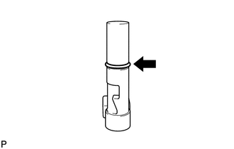
Coat a new O-ring with MP grease, and install it to the shift and select lever shaft straight pin (B).
-
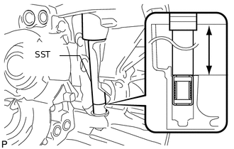
INSTALL SHIFT AND SELECT LEVER SHAFT STRAIGHT PIN
-
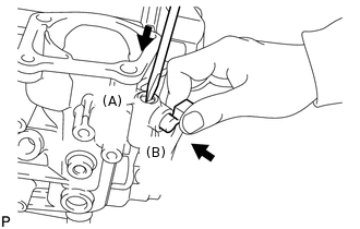
Install the spring.
While pressing in the shift and select lever shaft straight pin (A) in as far as it will go, push in the shift and select lever shaft straight pin (B) to install it.
-
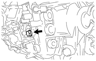
INSTALL MANUAL TRANSMISSION FILLER PLUG
-
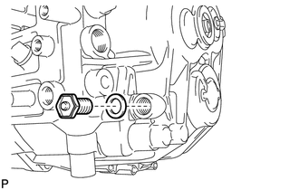
Install a new gasket and the manual transmission filler plug.
39.2 N*m
400 kgf*cm
29 ft.*lbf
-
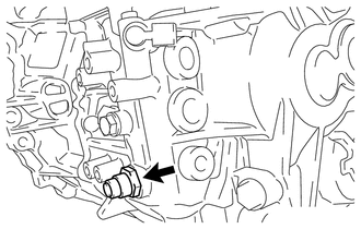
INSTALL DRAIN PLUG
-
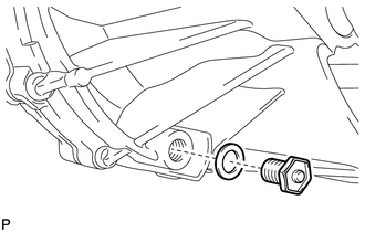
Install a new gasket and the drain plug.
39.2 N*m
400 kgf*cm
29 ft.*lbf
-
INSTALL TRANSMISSION CASE OIL SEAL
INSTALL TRANSAXLE CASE OIL SEAL
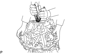
INSTALL SHIFT AND SELECT LEVER ASSEMBLY
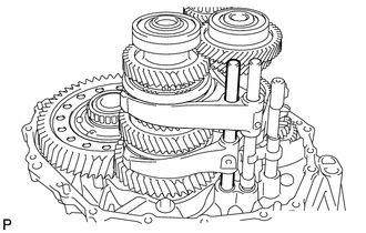
-
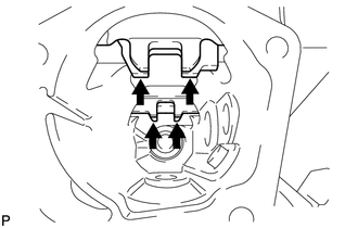
Align the 4 shift fork shafts as shown in the illustration.
Clean the contact surface of the manual transmission case and shift and select lever assembly.
Clean the threads of the bolts with non-residue solvent.
-
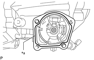
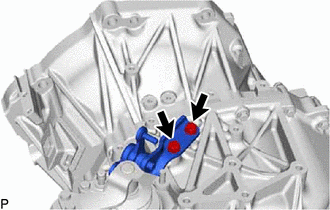
*a
Seal Packing
Apply seal packing to the manual transmission case as shown in the illustration.
Seal packing
Toyota Genuine Seal Packing 1281, Three Bond 1281 or equivalent
Apply a few drops of adhesive to 2 or 3 threads of the 4 bolts.
Adhesive
Toyota Genuine Adhesive 1344, Three Bond 1344 or equivalent
-
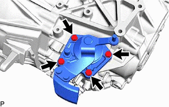
Install the shift and select lever assembly to the manual transmission case with the 4 bolts.
18.6 N*m
190 kgf*cm
14 ft.*lbf
-
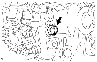
INSTALL SHIFT GATE PIN
-
Apply a few drops of the adhesive to 2 or 3 threads of the shift gate pin.
Adhesive
Toyota Genuine Adhesive 1344, Three Bond 1344 or equivalent
Install the shift gate pin to the manual transmission case.
30 N*m
306 kgf*cm
22 ft.*lbf
-
INSTALL NO. 2 LOCK BALL ASSEMBLY
Clean the threads of the No. 2 lock ball assembly with non-residue solvent.
-
Apply a few drops of the adhesive to 2 or 3 threads of the No. 2 lock ball assembly.
Adhesive
Toyota Genuine Adhesive 1344, Three Bond 1344 or equivalent
Install the No. 2 lock ball assembly to the manual transmission case.
29.4 N*m
300 kgf*cm
22 ft.*lbf
INSTALL NO. 1 LOCK BALL ASSEMBLY
Clean the threads of the No. 1 lock ball assembly with non-residue solvent.
-
Apply a few drops of the adhesive to 2 or 3 threads of the No. 1 lock ball assembly.
Adhesive
Toyota Genuine Adhesive 1344, Three Bond 1344 or equivalent
Install the No. 1 lock ball assembly to the manual transmission case.
39.2 N*m
400 kgf*cm
29 ft.*lbf
INSTALL NEUTRAL POSITION SWITCH
-
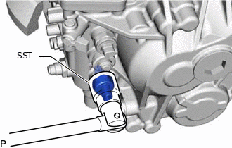
Using SST, install a new gasket and the neutral position switch to the manual transmission case.
09817-16011
40.2 N*m
410 kgf*cm
30 ft.*lbf
-
INSTALL BACK-UP LIGHT SWITCH ASSEMBLY
-
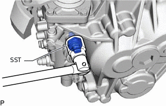
Using SST, install a new gasket and the back-up light switch assembly to the manual transmission case.
09817-16011
40.2 N*m
410 kgf*cm
30 ft.*lbf
-
INSTALL FLOOR SHIFT SELECTING BELL CRANK ASSEMBLY
-
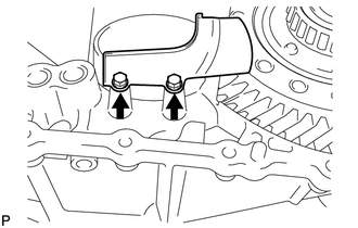
Install the floor shift selecting bell crank assembly to the manual transmission case with the 2 bolts.
20 N*m
204 kgf*cm
15 ft.*lbf
-
INSTALL CONTROL CABLE BRACKET
-
Install the control cable bracket to the manual transaxle assembly with the 3 bolts.
17 N*m
173 kgf*cm
13 ft.*lbf
-
INSTALL RELEASE FORK SUPPORT
INSTALL CLUTCH RELEASE FORK BOOT
-
Install the clutch release fork boot to the front transaxle assembly.
-
INSTALL CLUTCH RELEASE FORK SUB-ASSEMBLY
INSTALL CLUTCH RELEASE BEARING ASSEMBLY