OUTER REAR VIEW MIRROR DISASSEMBLY
CAUTION / NOTICE / HINT
Tech Tips
-
Use the same procedure for the RH and LH sides.
-
The procedure listed below is for the LH side.
PROCEDURE
-
REMOVE OUTER MIRROR LH
-
REMOVE NO. 2 OUTER MIRROR COVER LH
-
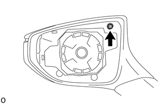
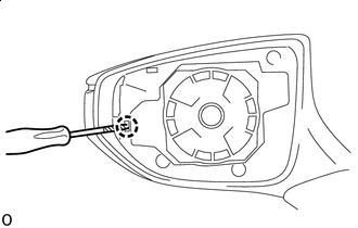
Remove the screw.
-
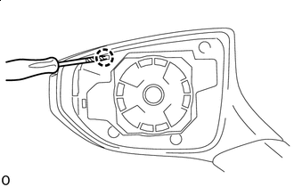

Protective Tape Using a thin-bladed screwdriver, detach the claw.
Tech Tips
Tape the thin-bladed screwdriver tip before use.
-

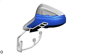
Remove in this Direction Detach the claw and remove the No. 2 outer mirror cover LH (visor cover A).
-
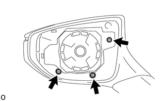
Remove the 3 screws.
-
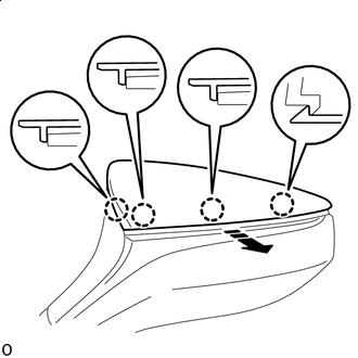
Protective Tape Using a thin-bladed screwdriver, detach the claw.
Tech Tips
Tape the thin-bladed screwdriver tip before use.
-
Remove in this Direction Remove the No. 2 outer mirror cover LH (visor cover B).
-
-
REMOVE SIDE TURN SIGNAL LIGHT ASSEMBLY LH
-
REMOVE SIDE TELEVISION CAMERA ASSEMBLY LH (w/ Panoramic View Monitor System)
-
REMOVE OUTER MIRROR ACTUATOR ASSEMBLY LH
-
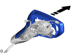
Remove in this Direction Remove the visor cover assembly LH from the outer mirror actuator assembly LH.
-