INTEGRATION RELAY ON-VEHICLE INSPECTION
PROCEDURE
-
INSPECT NO. 1 INTEGRATION RELAY
Tech Tips
-
This inspection is not for the No. 1 integration relay itself, but for the wire harness that is connected to the No. 1 integration relay. If the result is within the specified condition, the No. 1 integration relay may be malfunctioning.
-
If the result is not as specified, a short between No. 1 integration relay and one of the electrical loads is suspected.
-
Make sure that the malfunction is reproduced when performing the inspection below.
-
After the wire harness has been repaired, disconnect all connectors that are connected to the No. 1 integration relay, and turn the power switch on (READY) to clear the DTCs.
-
Diagnosis Terminal
-
Confirm that the system that is malfunctioning.
-
Make sure that the malfunction is reproduced.
-
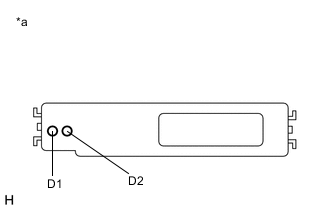
Text in Illustration *a Component with harness connected
(No. 1 Integration Relay)
Measure the voltage according to the value(s) in the table below.
Standard Voltage Tester Connection Condition Specified Condition D1 - Body ground Power switch on (IG) or (READY) 3.5 to 5.0 V D2 - Body ground Power switch on (IG) or (READY) 3.5 to 5.0 V If the result is not as specified, a short between No. 1 integration relay and one of the electrical loads is suspected.
-
-