WIPER AND WASHER SYSTEM Washer Motor Circuit
DESCRIPTION
When the washer motor and pump assembly receives signals from the windshield wiper switch assembly it operates to spray washer fluid from the washer nozzle sub-assemblies.
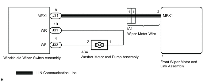
WIRING DIAGRAM
-
for Wiper Switch RH Side Type:

-
for Wiper Switch LH Side Type:
PROCEDURE
-
READ VALUE USING GTS
-
Connect the GTS to the DLC3.
-
Turn the engine switch on (IG).
-
Turn the GTS on.
-
Enter the following menus: Body Electrical / Wiper / Data List.
-
Read the Data List according to the display on the GTS.
Body Electrical > Wiper > Data ListTester Display Measurement Item Range Normal Condition Diagnostic Note Washer Switch Washer switch ON position signal ON or OFF ON: Front washer switch in ON position
OFF: Front washer switch not in ON position
-
Body Electrical > Wiper > Data ListTester Display Washer Switch OK The GTS display changes correctly in response to the front washer switch operation. Result Proceed to OK NG
NG 
REPLACE WINDSHIELD WIPER SWITCH ASSEMBLY Click here
OK 
-
-
INSPECT WASHER MOTOR AND PUMP ASSEMBLY
-
Inspect the washer motor and pump assembly.
Result Proceed to OK NG
NG
REPLACE WASHER MOTOR AND PUMP ASSEMBLY Click here
OK
-
-
CHECK HARNESS AND CONNECTOR (WASHER MOTOR AND PUMP ASSEMBLY - WINDSHIELD WIPER SWITCH ASSEMBLY)
-
Disconnect the A34 washer motor and pump assembly connector.
-
Disconnect the J31 windshield wiper switch assembly connector.
-
Disconnect the J33 windshield wiper switch assembly connector.
-
Measure the resistance according to the value(s) in the table below.
Standard Resistance for Wiper Switch RH Side Type Tester Connection Condition Specified Condition J31-5 (WR) - A34-1 Always Below 1 Ω J33-7 (WF) - A34-2 Always Below 1 Ω J31-5 (WR) or A34-1 - Body ground Always 10 kΩ or higher J33-7 (WF) or A34-2 - Body ground Always 10 kΩ or higher for Wiper Switch LH Side Type Tester Connection Condition Specified Condition J31-10 (WR) - A34-1 Always Below 1 Ω J33-4 (WF) - A34-2 Always Below 1 Ω J31-10 (WR) or A34-1 - Body ground Always 10 kΩ or higher J33-4 (WF) or A34-2 - Body ground Always 10 kΩ or higher Result Proceed to OK NG
OK
REPLACE WINDSHIELD WIPER SWITCH ASSEMBLY Click here
NG
REPAIR OR REPLACE HARNESS OR CONNECTOR
-