AIRBAG SYSTEM, Diagnostic DTC:B1815/54,B1816/54,B1817/54 and B1818/54
| DTC Code | DTC Name |
|---|---|
| B1815/54 | Short in Front Passenger Side Squib 2nd Step Circuit |
| B1816/54 | Open in Front Passenger Side Squib 2nd Step Circuit |
| B1817/54 | Short to GND in Front Passenger Side Squib 2nd Step Circuit |
| B1818/54 | Short to B+ in Front Passenger Side Squib 2nd Step Circuit |
DESCRIPTION
The front passenger side squib 2nd step circuit consists of the center airbag sensor and instrument panel passenger airbag.
The circuit instructs the SRS to deploy when deployment conditions are met.
These DTCs are stored when a malfunction is detected in the front passenger side squib 2nd step circuit.
DTC No. |
Detection Item |
DTC Detection Condition |
Trouble Area |
Test Mode / Check Mode |
|---|---|---|---|---|
B1815/54 |
Short in Front Passenger Side Squib 2nd Step Circuit |
One of the following conditions is met:
|
|
*2 |
B1816/54 |
Open in Front Passenger Side Squib 2nd Step Circuit |
One of the following conditions is met:
|
|
*2 |
B1817/54 |
Short to GND in Front Passenger Side Squib 2nd Step Circuit |
One of the following conditions is met:
|
|
*2 |
B1818/54 |
Short to B+ in Front Passenger Side Squib 2nd Step Circuit |
One of the following conditions is met:
|
|
*2 |
WIRING DIAGRAM
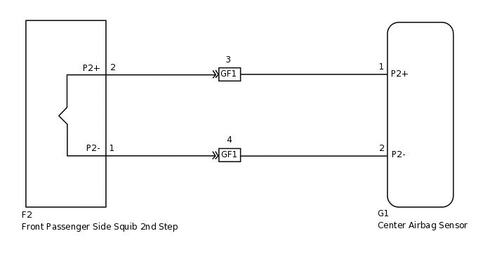
CAUTION / NOTICE / HINT
After turning the engine switch off, waiting time may be required before disconnecting the cable from the battery terminal. Therefore, make sure to read the disconnecting the cable from the battery terminal notice before proceeding with work (Click here).
When disconnecting the cable from the negative (-) battery terminal while performing repairs, some systems need to be initialized after the cable is reconnected (Click here).
To perform the simulation method, enter check mode (signal check) with the intelligent tester (Click here), and then wiggle each connector of the airbag system or drive the vehicle on various types of road (Click here).
PROCEDURE
CHECK INSTRUMENT PANEL PASSENGER AIRBAG (FRONT PASSENGER SIDE SQUIB 2ND STEP)
-
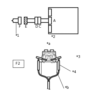
*1
Front Passenger Side Squib 2nd Step
*2
Center Airbag Sensor
*3
Connector E
*4
SST
*a
Front view of wire harness connector
(to Front Passenger Side Squib 2nd Step)
*b
Color: Black
Turn the engine switch off.
Disconnect the cable from the negative (-) battery terminal, and wait for at least 90 seconds.
Disconnect the connectors from the steering pad.
Connect the white wire side of SST (resistance: 2.1 Ω) to connector E (black connector).
CAUTION:Never connect the tester to the instrument panel passenger airbag (front passenger side squib 2nd step) for measurement, as this may lead to a serious injury due to airbag deployment.
Note:Do not forcibly insert SST into the terminals of the connector when connecting SST.
Insert SST straight into the terminals of the connector.
Connect the cable to the negative (-) battery terminal, and wait for at least 2 seconds.
Turn the engine switch on (IG), and wait for at least 60 seconds.
Clear the DTCs.
Body Electrical > SRS Airbag > Clear DTCs
Turn the engine switch off.
Turn the engine switch on (IG), and wait for at least 60 seconds.
Check for DTCs.
Body Electrical > SRS Airbag > Trouble Codes
OK
DTC B1815, B1816, B1817 or B1818 is not output.
Tip:Codes other than DTC B1815, B1816, B1817 and B1818 may be output at this time, but they are not related to this check.
Result
Result
OK
NG
09843-18061
-
CHECK CONNECTOR
-
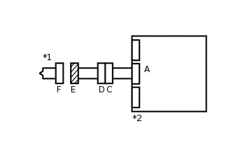
*1
Front Passenger Side Squib 2nd Step
*2
Center Airbag Sensor
Turn the engine switch off.
Disconnect the cable from the negative (-) battery terminal, and wait for at least 90 seconds.
Disconnect SST from connector E.
Check that the spiral cable connectors (on the steering pad side) are not damaged.
OK
The lock button is not disengaged, and the claw of the lock is not damaged or deformed.
Result
Result
OK
NG
NG REPLACE NO. 2 INSTRUMENT PANEL WIRE
-
CHECK FRONT PASSENGER SIDE SQUIB 2ND STEP CIRCUIT
-
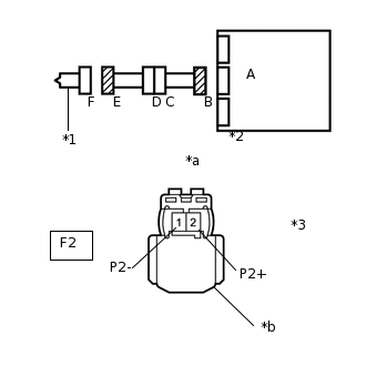
*1
Front Passenger Side Squib 2nd Step
*2
Center Airbag Sensor
*3
Connector E
*a
Front view of wire harness connector
(to Front Passenger Side Squib 2nd Step)
*b
Color: Black
Disconnect the connectors from the center airbag sensor.
Connect the cable to the negative (-) battery terminal, and wait for at least 2 seconds.
Measure the voltage according to the value(s) in the table below.
Standard Voltage
Tester Connection
Switch Condition
Specified Condition
F2-2 (P2+) - Body ground
Engine switch on (IG)
Below 1 V
F2-1 (P2-) - Body ground
Engine switch on (IG)
Below 1 V
Turn the engine switch off.
Disconnect the cable from the negative (-) battery terminal, and wait for at least 90 seconds.
Measure the resistance according to the value(s) in the table below.
Standard Resistance
Tester Connection
Condition
Specified Condition
F2-2 (P2+) - F2-1 (P2-)
Always
Below 1 Ω
Release the activation prevention mechanism built into connector B.
Measure the resistance according to the value(s) in the table below.
Standard Resistance
Tester Connection
Condition
Specified Condition
F2-2 (P2+) - F2-1 (P2-)
Always
1 MΩ or higher
F2-2 (P2+) - Body ground
Always
1 MΩ or higher
F2-1 (P2-) - Body ground
Always
1 MΩ or higher
Result
Result
OK
NG
NG CHECK INSTRUMENT PANEL WIRE (CENTER AIRBAG SENSOR - NO. 2 INSTRUMENT PANEL WIRE)Click here
-
CHECK CENTER AIRBAG SENSOR
-
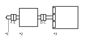
*1
Front Passenger Side Squib 2nd Step
*2
Center Airbag Sensor
Connect the connectors to the steering pad and center airbag sensor.
Connect the cable to the negative (-) battery terminal, and wait for at least 2 seconds.
Turn the engine switch on (IG), and wait for at least 60 seconds.
Clear the DTCs.
Body Electrical > SRS Airbag > Clear DTCs
Turn the engine switch off.
Turn the engine switch on (IG), and wait for at least 60 seconds.
Clear the DTCs.
Body Electrical > SRS Airbag > Trouble Codes
OK
DTC B1815, B1816, B1817 or B1818 is not output.
Tip:Codes other than DTC B1815, B1816, B1817 and B1818 may be output at this time, but they are not related to this check.
Result
Result
OK
NG
-
CHECK INSTRUMENT PANEL WIRE (CENTER AIRBAG SENSOR - NO. 2 INSTRUMENT PANEL WIRE)
-
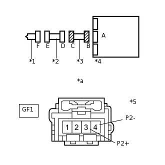
*1
Front Passenger Side Squib 2nd Step
*2
No. 2 Instrument Panel Wire
*3
Instrument Panel Wire
*4
Center Airbag Sensor
*5
Connector C
*a
Front view of wire harness connector
(to No. 2 Instrument Panel Wire)
Restore the released activation prevention mechanism of connector B to its original condition.
Disconnect the instrument panel wire connector from the No. 2 instrument panel wire.
Connect the cable to the negative (-) battery terminal, and wait for at least 2 seconds.
Measure the voltage according to the value(s) in the table below.
Standard Voltage
Tester Connection
Switch Condition
Specified Condition
GF1-3 (P2+) - Body ground
Engine switch on (IG)
Below 1 V
GF1-4 (P2-) - Body ground
Engine switch on (IG)
Below 1 V
Turn the engine switch off.
Disconnect the cable from the negative (-) battery terminal, and wait for at least 90 seconds.
Measure the resistance according to the value(s) in the table below.
Standard Resistance
Tester Connection
Condition
Specified Condition
GF1-3 (P2+) - GF1-4 (P2-)
Always
Below 1 Ω
Release the activation prevention mechanism built into connector B.
Measure the resistance according to the value(s) in the table below.
Standard Resistance
Tester Connection
Condition
Specified Condition
GF1-3 (P2+) - GF1-4 (P2-)
Always
1 MΩ or higher
GF1-3 (P2+) - Body ground
Always
1 MΩ or higher
GF1-4 (P2-) - Body ground
Always
1 MΩ or higher
Result
Result
OK
NG
OK REPLACE NO. 2 INSTRUMENT PANEL WIRE
NG REPLACE INSTRUMENT PANEL WIRE
-