LANE DEPARTURE ALERT SYSTEM, Diagnostic DTC:C1AA0
| DTC Code | DTC Name |
|---|---|
| C1AA0 | Front Camera Module Circuit |
DESCRIPTION
DTC C1AA0 is stored when the pre-crash safety city sensor detects an internal circuit malfunction.
DTC No. |
Detection Item |
DTC Detection Condition |
Trouble Area |
|---|---|---|---|
C1AA0 |
Front Camera Module Circuit |
When the ignition switch is ON and the lane departure alert system is enabled, the pre-crash safety city sensor detects an internal circuit malfunction for 5 seconds or more. |
|
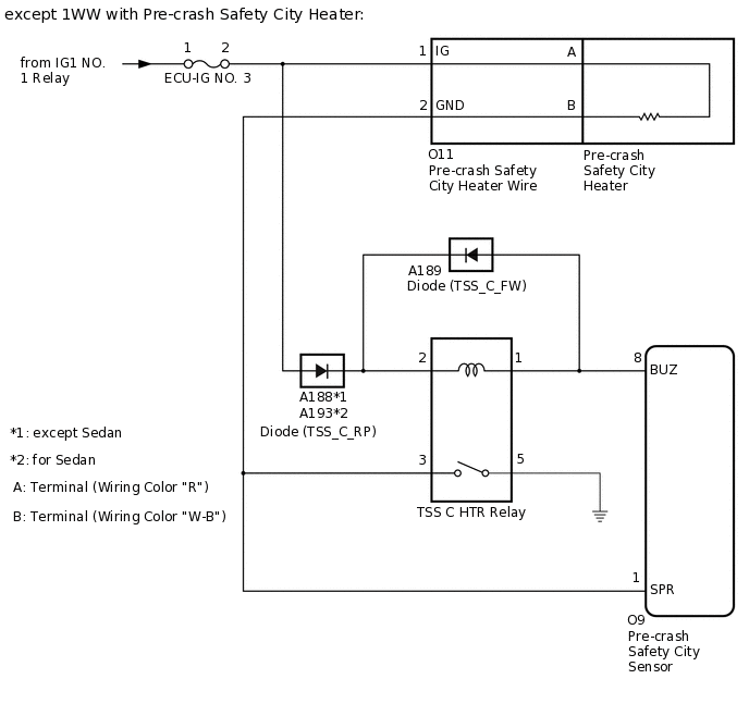
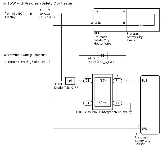
WIRING DIAGRAM
CAUTION / NOTICE / HINT
w/ Pre-crash Safety City Heater:
Inspect the fuses for circuits related to this system before performing the following procedure.
When replacing the pre-crash safety city sensor, replace it with a new one and be sure to perform initialization. If a pre-crash safety city sensor which was installed to another vehicle is used, the information stored in the pre-crash safety city sensor will not match the information from the vehicle and, as a result, a DTC may be stored.
If the pre-crash safety city sensor has been replaced, or the windshield glass has been replaced or removed/installed, be sure to perform Recognition Camera/Target Position Memory and Recognition Camera Axis Adjust.
PROCEDURE
CHECK FOR DTCS
Check if the stored DTCs are current DTCs.
Check for DTCs.
Chassis > PCS/LDA/RSA/LVN > Trouble Codes
Result
Result
Proceed to
DTC C1AA0 is not output
A
DTC C1AA0 is output (w/ Pre-crash Safety City Heater)
B
DTC C1AA0 is output (w/o Pre-crash Safety City Heater)
C
C REPLACE PRE-CRASH SAFETY CITY SENSORClick here
CHECK HARNESS AND CONNECTOR (TSS C HTR RELAY COIL CIRCUIT)
Remove the ECU-IG NO. 3 fuse from the instrument panel junction block assembly.
except 1WW:
Remove the TSS C HTR relay.
Measure the resistance according to the value(s) in the table below.
Standard Resistance
Tester Connection
Condition
Specified Condition
ECU-IG NO. 3 fuse holder terminal 2 - TSS C HTR relay holder terminal 2
Positive (+) tester probe → ECU-IG NO. 3 fuse holder terminal 2
Negative (-) tester probe → TSS C HTR relay holder terminal 2
Always
Below 1 Ω
Negative (-) tester probe → ECU-IG NO. 3 fuse holder terminal 2
Positive (+) tester probe → TSS C HTR relay holder terminal 2
Always
10 kΩ or higher
Disconnect the O9 pre-crash safety city sensor connector.
Measure the resistance according to the value(s) in the table below.
Standard Resistance
Tester Connection
Condition
Specified Condition
O9-8 (BUZ) - TSS C HTR relay holder terminal 2
Positive (+) tester probe → O9-8 (BUZ)
Negative (-) tester probe → TSS C HTR relay holder terminal 2
Always
Below 1 Ω
Negative (-) tester probe → O9-8 (BUZ)
Positive (+) tester probe → TSS C HTR relay holder terminal 2
Always
10 kΩ or higher
for 1WW:
Remove the EDU relay (No. 1 integration relay).
Measure the resistance according to the value(s) in the table below.
Standard Resistance
Tester Connection
Condition
Specified Condition
ECU-IG NO. 3 fuse holder terminal 2 - 1J-7
Positive (+) tester probe → ECU-IG NO. 3 fuse holder terminal 2
Negative (-) tester probe → 1J-7
Always
Below 1 Ω
Negative (-) tester probe → ECU-IG NO. 3 fuse holder terminal 2
Positive (+) tester probe → 1J-7
Always
10 kΩ or higher
Disconnect the O9 pre-crash safety city sensor connector.
Measure the resistance according to the value(s) in the table below.
Standard Resistance
Tester Connection
Condition
Specified Condition
O9-8 (BUZ) - 1J-7
Positive (+) tester probe → O9-8 (BUZ)
Negative (-) tester probe → 1J-7
Always
Below 1 Ω
Negative (-) tester probe → O9-8 (BUZ)
Positive (+) tester probe → 1J-7
Always
10 kΩ or higher
Result
Proceed to
OK
NG
NG REPAIR OR REPLACE HARNESS OR CONNECTOR (TSS C HTR RELAY COIL CIRCUIT)Click here
REPLACE PRE-CRASH SAFETY CITY SENSOR
Replace the pre-crash safety city sensor.
Perform the "Recognition Camera/Target Position Memory" and "Recognition Camera Axis Adjust" of pre-crash safety city sensor.
Result
Proceed to
NEXT
NEXT END
REPAIR OR REPLACE HARNESS OR CONNECTOR (TSS C HTR RELAY COIL CIRCUIT)
Repair or replace the harness or connector.
Result
Proceed to
NEXT
REPLACE PRE-CRASH SAFETY CITY SENSOR
Replace the pre-crash safety city sensor.
Perform the "Recognition Camera/Target Position Memory" and "Recognition Camera Axis Adjust" of pre-crash safety city sensor.
Result
Proceed to
NEXT
NEXT END