REAR CRANKSHAFT OIL SEAL (w/ Dual VVT-i) INSTALLATION

-
INSTALL REAR CRANKSHAFT OIL SEAL
-
Apply MP grease to a new rear crankshaft oil seal lip.
Note
Keep the lip free from foreign matter.
-
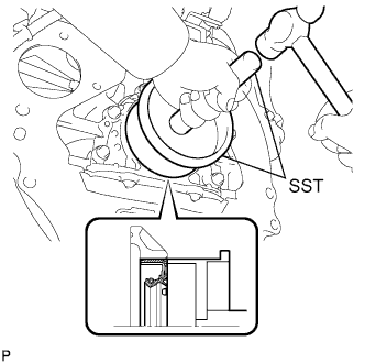
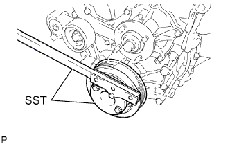
Using SST and a hammer, tap in the rear crankshaft oil seal until its surface is flush with the rear oil seal retainer edge.
- SST
- 09223-15030
- 09950-70010 ( 09951-07150 )
Note
Wipe off extra grease from the crankshaft.
-
-
INSTALL FLYWHEEL SUB-ASSEMBLY (for Manual Transmission)
Tech Tips
If any one of the mounting bolts is broken or deformed, replace it.
-
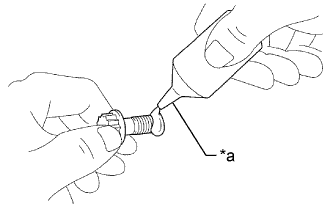
Text in Illustration *a Adhesive Apply adhesive to 2 or 3 threads of the mounting bolt end.
Adhesive Toyota Genuine Adhesive 1324, Three Bond 1324 or equivalent -
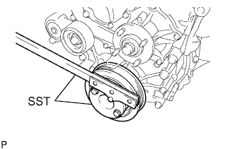
Fix the crankshaft with SST.
- SST
- 09213-54015 ( 91651-60855 )
- 09330-00021
-
Temporarily install the flywheel with 10 new mounting bolts.
-
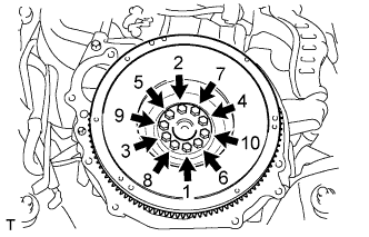
Install and uniformly tighten the 10 mounting bolts in several steps in the sequence shown in the illustration.
- Torque:
- 27 N*m { 270 kgf*cm, 20 ft.*lbf }
If any one of the mounting bolts does not meet the torque specification, replace the mounting bolt.
-
Mark the top of the bolts with paint.
-
Tighten the 10 bolts 90° in the same sequence.
-
Check that the paint marks are now at a 90° angle to the top.
-
-
INSTALL DRIVE PLATE AND RING GEAR SUB-ASSEMBLY (for Automatic Transmission)
-
Using SST, hold the crankshaft.
- SST
- 09213-54015 ( 91651-60855 )
- 09330-00021
-
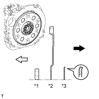
Text in Illustration *1 Front Drive Plate Spacer (Reversible) *2 Drive Plate and Ring Gear Sub-assembly *3 Rear Drive Plate Spacer 
Transmission Side 
Engine Side Install the front drive plate spacer, drive plate and ring gear sub-assembly and rear drive plate spacer to the crankshaft.
Tech Tips
-
The front drive plate spacer is reversible.
-
As the rear drive plate spacer and drive plate and ring gear sub-assembly are not reversible, be sure to install it so that it is facing in the direction shown in the illustration.
-
-
Clean the bolts and bolt holes.
-
Apply adhesive to 2 or 3 threads at the end of each of the 10 bolts.
Adhesive Toyota Genuine Adhesive 1324, Three Bond 1324 or equivalent -
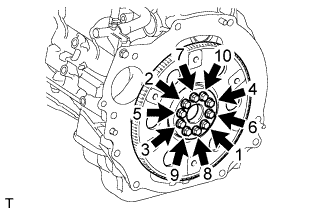
Install and uniformly tighten the 10 bolts in several steps in the sequence shown in the illustration.
- Torque:
- 74 N*m { 755 kgf*cm, 55 ft.*lbf }
Note
Do not start the engine for at least an hour after installing the drive plate and ring gear sub-assembly.
-
-
INSTALL CLUTCH DISC ASSEMBLY (for Manual Transmission)
-
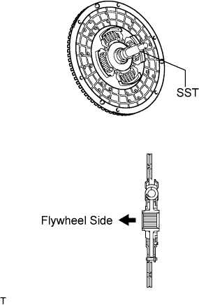
Insert SST into the clutch disc assembly, then insert them into the flywheel sub-assembly.
- SST
- 09301-00110
Note
Take care not to insert the clutch disc assembly in the wrong direction.
-
-
INSTALL CLUTCH COVER ASSEMBLY (for Manual Transmission)
-
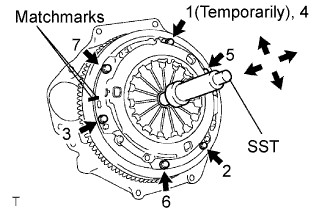
Align the matchmark on the clutch cover assembly with the one on the flywheel sub-assembly.
-
Following the procedures shown in the illustration, tighten the 6 bolts starting from the bolt located near the knock pin on the top.
- SST
- 09301-00110
- Torque:
- 19 N*m { 195 kgf*cm, 14 ft.*lbf }
Tech Tips
-
Evenly tighten the bolts by following the order shown in the illustration.
-
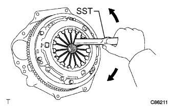
Tighten the bolts after checking that the disc is in the center by lightly moving the SST up and down, left and right.
-
-
INSPECT AND ADJUST CLUTCH COVER ASSEMBLY (for Manual Transmission)
-
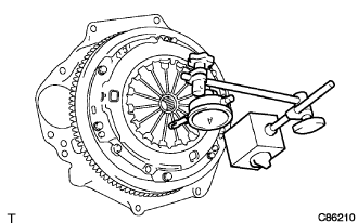
Using a dial indicator with a roller instrument, check the diaphragm spring tip alignment.
Maximum non-alignment 0.9 mm (0.035 in.) -
If alignment is not as specified, adjust the diaphragm spring tip alignment using SST.
- SST
- 09333-00013
-
-
INSTALL MANUAL TRANSMISSION ASSEMBLY (for Manual Transmission)
-
INSTALL AUTOMATIC TRANSMISSION ASSEMBLY (for Automatic Transmission)