PRE-CRASH SAFETY SYSTEM, Diagnostic DTC:C1A4B
| DTC Code | DTC Name |
|---|---|
| C1A4B | Stop Light Relay Circuit |
DESCRIPTION
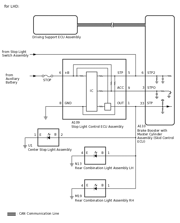
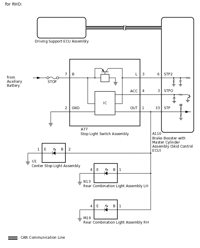
The brake booster with master cylinder assembly (skid control ECU) sends a stop light operation signal to the stop light switch assembly. When the brake booster with master cylinder assembly (skid control ECU) detects a malfunction in the stop light circuit, the driving support ECU assembly stores DTC C1A4B.
DTC No. |
Detection Item |
DTC Detection Condition |
Trouble Area |
|---|---|---|---|
C1A4B |
Stop Light Relay Circuit |
Either of the following conditions is met:
|
|
WIRING DIAGRAM
CAUTION / NOTICE / HINT
Inspect the fuses for circuits related to this system before performing the following procedure.
When replacing the brake booster with master cylinder assembly (skid control ECU), perform zero point calibration.
When the entry and start function does not operate, check the entry and start system (start function).
PROCEDURE
CHECK STOP LIGHT OPERATION
Check that the stop lights come on when the brake pedal is depressed and go off when the brake pedal is released.
OK
Condition
Illumination Condition
Brake pedal depressed
On
Brake pedal released
Off
Result
Result
Proceed to
OK (for LHD)
A
OK (for RHD)
B
NG
C
CHECK HARNESS AND CONNECTOR (STPO TERMINAL VOLTAGE)
Turn the power switch off.
-
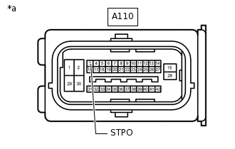
*a
Front view of wire harness connector
(to Brake Booster with Master Cylinder Assembly [Skid Control ECU])
Disconnect the brake booster with master cylinder assembly (skid control ECU) connector.
Measure the voltage according to the value(s) in the table below.
Standard Voltage
Tester Connection
Condition
Specified Condition
A110-3 (STPO) - Body ground
Always
11 to 14 V
Result
Proceed to
OK
NG
NG CHECK HARNESS AND CONNECTOR (STOP LIGHT CONTROL ECU ASSEMBLY - BRAKE BOOSTER WITH MASTER CYLINDER ASSEMBLY [SKID CONTROL ECU])Click here
PERFORM ACTIVE TEST USING GTS (STOP LIGHT RELAY)
Enter the following menus: Chassis / ABS/VSC/TRC / Active Test.
Perform "Active Test" according to the display on GTS.
Chassis > ABS/VSC/TRC > Active Test
Tester Display
Measurement Item
Control Range
Diagnostic Note
Stop Light Relay
Stop lights
ON or OFF
Test possible at vehicle speed of 0 km/h (0 mph)
Chassis > ABS/VSC/TRC > Active Test
Tester Display
Stop Light Relay
Enter the following menus: Chassis / ABS/VSC/TRC / Data List.
Check the stop light switch assembly operation using the Data List and stop light operation by performing an Active Test.
Chassis > ABS/VSC/TRC > Data List
Tester Display
Measurement Item
Range
Normal Condition
Diagnostic Note
Stop Light Relay Output
Stop light control relay output
ON or OFF
ON: Relay output on (Stop light on)
OFF: Relay output off (Stop light off)
-
Chassis > ABS/VSC/TRC > Data List
Tester Display
Stop Light Relay
Result
Result
Proceed to
When Active Test performed, Data List item not changes between ON and OFF
A
When Active Test performed, Data List item changes between ON and OFF and stop lights turn on and off
B
B CHECK HARNESS AND CONNECTOR (STOP LIGHT CONTROL ECU ASSEMBLY - BRAKE BOOSTER WITH MASTER CYLINDER ASSEMBLY [SKID CONTROL ECU])Click here
INSPECT BRAKE BOOSTER WITH MASTER CYLINDER ASSEMBLY (SKID CONTROL ECU)
Enter the following menus: Chassis / ABS/VSC/TRC / Active Test.
Perform "Active Test" according to the display on GTS.
Chassis > ABS/VSC/TRC > Active Test
Tester Display
Measurement Item
Control Range
Diagnostic Note
Stop Light Relay
Stop lights
ON or OFF
Test possible at vehicle speed of 0 km/h (0 mph)
Chassis > ABS/VSC/TRC > Active Test
Tester Display
Stop Light Relay
-
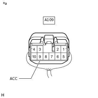
*a
Component with harness connected
(Stop Light Control ECU Assembly)
Measure the voltage according to the value(s) in the table below.
Standard Voltage
Tester Connection
Condition
Specified Condition
A109-9 (ACC) - Body ground
Active test is OFF
11 to 14 V
A109-9 (ACC) - Body ground
Active test is ON
Below 1.5 V
Result
Proceed to
OK
NG
REPLACE STOP LIGHT CONTROL ECU ASSEMBLY
Replace the stop light control ECU assembly.
Result
Proceed to
NEXT
CHECK FOR DTC
Clear the DTCs.
Chassis > ABS/VSC/TRC > Clear DTCs
Enter the following menus: Chassis / ABS/VSC/TRC / Active Test.
Tip:If the detection conditions are not met, the system cannot detect the malfunction.
Using the GTS, perform the Active Test "Stop Light Relay" with the power switch on (IG).
Perform "Active Test" according to the display on the GTS.
Chassis > ABS/VSC/TRC > Active Test
Tester Display
Measurement Item
Control Range
Diagnostic Note
Stop Light Relay
Stop lights
ON or OFF
Test possible at vehicle speed of 0 km/h (0 mph)
Chassis > ABS/VSC/TRC > Active Test
Tester Display
Stop Light Relay
Check for DTCs.
Chassis > ABS/VSC/TRC > Trouble Codes
Result
Result
Proceed to
DTC C1380 is output
A
DTC C1380 is not output
B
B END (STOP LIGHT CONTROL ECU ASSEMBLY WAS DEFECTIVE)
CHECK HARNESS AND CONNECTOR (STOP LIGHT CONTROL ECU ASSEMBLY - BRAKE BOOSTER WITH MASTER CYLINDER ASSEMBLY [SKID CONTROL ECU])
Disconnect the A110 brake booster with master cylinder assembly (skid control ECU) connector.
Disconnect the A109 stop light control ECU assembly connector.
Measure the resistance according to the value(s) in the table below.
Standard Resistance
Tester Connection
Condition
Specified Condition
A110-33 (STP) - A109-1 (OUT)
Always
Below 1 Ω
A110-33 (STP) or A109-1 (OUT) - Body ground
Always
10 kΩ or higher
Result
Proceed to
OK
NG
NG REPAIR OR REPLACE HARNESS OR CONNECTOR
REPLACE BRAKE BOOSTER WITH MASTER CYLINDER ASSEMBLY (SKID CONTROL ECU)
Replace the brake booster with master cylinder assembly (skid control ECU).
Result
Proceed to
NEXT
NEXT CHECK FOR DTCClick here
CHECK HARNESS AND CONNECTOR (STOP LIGHT CONTROL ECU ASSEMBLY - BRAKE BOOSTER WITH MASTER CYLINDER ASSEMBLY [SKID CONTROL ECU])
Disconnect the A110 brake booster with master cylinder assembly (skid control ECU) connector.
Disconnect the A109 stop light control ECU assembly connector.
Measure the resistance according to the value(s) in the table below.
Standard Resistance
Tester Connection
Condition
Specified Condition
A110-3 (STPO) - A109-9 (ACC)
Always
Below 1 Ω
A110-3 (STPO) or A109-9 (ACC) - Body ground
Always
10 kΩ or higher
Result
Proceed to
OK
NG
NG REPAIR OR REPLACE HARNESS OR CONNECTOR
REPLACE BRAKE BOOSTER WITH MASTER CYLINDER ASSEMBLY (SKID CONTROL ECU)
Replace the brake booster with master cylinder assembly (skid control ECU).
Result
Proceed to
NEXT
NEXT CHECK FOR DTCClick here
CHECK HARNESS AND CONNECTOR (STPO TERMINAL VOLTAGE)
Turn the power switch off.
-

*a
Front view of wire harness connector
(to Brake Booster with Master Cylinder Assembly [Skid Control ECU])
Disconnect the brake booster with master cylinder assembly (skid control ECU) connector.
Measure the voltage according to the value(s) in the table below.
Standard Voltage
Tester Connection
Condition
Specified Condition
A110-3 (STPO) - Body ground
Always
11 to 14 V
Result
Proceed to
OK
NG
NG CHECK HARNESS AND CONNECTOR (STOP LIGHT SWITCH ASSEMBLY - BRAKE BOOSTER WITH MASTER CYLINDER ASSEMBLY [SKID CONTROL ECU])Click here
PERFORM ACTIVE TEST USING GTS (STOP LIGHT RELAY)
Enter the following menus: Chassis / ABS/VSC/TRC / Active Test.
Perform "Active Test" according to the display on GTS.
Chassis > ABS/VSC/TRC > Active Test
Tester Display
Measurement Item
Control Range
Diagnostic Note
Stop Light Relay
Stop lights
ON or OFF
Test possible at vehicle speed of 0 km/h (0 mph)
Chassis > ABS/VSC/TRC > Active Test
Tester Display
Stop Light Relay
Enter the following menus: Chassis / ABS/VSC/TRC / Data List.
Check the stop light switch assembly operation using the Data List and stop light operation by performing an Active Test.
Chassis > ABS/VSC/TRC > Data List
Tester Display
Measurement Item
Range
Normal Condition
Diagnostic Note
Stop Light Relay Output
Stop light control relay output
ON or OFF
ON: Relay output on (Stop light on)
OFF: Relay output off (Stop light off)
-
Chassis > ABS/VSC/TRC > Data List
Tester Display
Stop Light Relay
Result
Result
Proceed to
When Active Test performed, Data List item not changes between ON and OFF
A
When Active Test performed, Data List item changes between ON and OFF and stop lights turn on and off
B
B CHECK HARNESS AND CONNECTOR (STOP LIGHT SWITCH ASSEMBLY - BRAKE BOOSTER WITH MASTER CYLINDER ASSEMBLY [SKID CONTROL ECU])Click here
INSPECT BRAKE BOOSTER WITH MASTER CYLINDER ASSEMBLY (SKID CONTROL ECU)
Enter the following menus: Chassis / ABS/VSC/TRC / Active Test.
Perform "Active Test" according to the display on GTS.
Chassis > ABS/VSC/TRC > Active Test
Tester Display
Measurement Item
Control Range
Diagnostic Note
Stop Light Relay
Stop lights
ON or OFF
Test possible at vehicle speed of 0 km/h (0 mph)
Chassis > ABS/VSC/TRC > Active Test
Tester Display
Stop Light Relay
-
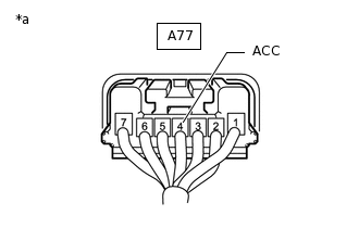
*a
Component with harness connected
(Stop Light Switch Assembly)
Measure the voltage according to the value(s) in the table below.
Standard Voltage
Tester Connection
Condition
Specified Condition
A77-4 (ACC) - Body ground
Active test is OFF
11 to 14 V
A77-4 (ACC) - Body ground
Active test is ON
Below 1.5 V
Result
Proceed to
OK
NG
REPLACE STOP LIGHT SWITCH ASSEMBLY
Replace the stop light switch assembly.
Result
Proceed to
NEXT
CHECK FOR DTC
Clear the DTCs.
Chassis > ABS/VSC/TRC > Clear DTCs
Enter the following menus: Chassis / ABS/VSC/TRC / Active Test.
Tip:If the detection conditions are not met, the system cannot detect the malfunction.
Using the GTS, perform the Active Test "Stop Light Relay" with the power switch on (IG).
Perform "Active Test" according to the display on the GTS.
Chassis > ABS/VSC/TRC > Active Test
Tester Display
Measurement Item
Control Range
Diagnostic Note
Stop Light Relay
Stop lights
ON or OFF
Test possible at vehicle speed of 0 km/h (0 mph)
Chassis > ABS/VSC/TRC > Active Test
Tester Display
Stop Light Relay
Check for DTCs.
Chassis > ABS/VSC/TRC > Trouble Codes
Result
Result
Proceed to
DTC C1380 is output
A
DTC C1380 is not output
B
B END (STOP LIGHT SWITCH ASSEMBLY WAS DEFECTIVE)
CHECK HARNESS AND CONNECTOR (STOP LIGHT SWITCH ASSEMBLY - BRAKE BOOSTER WITH MASTER CYLINDER ASSEMBLY [SKID CONTROL ECU])
Disconnect the A110 brake booster with master cylinder assembly (skid control ECU) connector.
Disconnect the A77 stop light switch assembly connector.
Measure the resistance according to the value(s) in the table below.
Standard Resistance
Tester Connection
Condition
Specified Condition
A110-33 (STP) - A77-1 (OUT)
Always
Below 1 Ω
Result
Proceed to
OK
NG
NG REPAIR OR REPLACE HARNESS OR CONNECTOR
REPLACE BRAKE BOOSTER WITH MASTER CYLINDER ASSEMBLY (SKID CONTROL ECU)
Replace the brake booster with master cylinder assembly (skid control ECU).
Result
Proceed to
NEXT
NEXT CHECK FOR DTCClick here
CHECK HARNESS AND CONNECTOR (STOP LIGHT SWITCH ASSEMBLY - BRAKE BOOSTER WITH MASTER CYLINDER ASSEMBLY [SKID CONTROL ECU])
Disconnect the A110 brake booster with master cylinder assembly (skid control ECU) connector.
Disconnect the A77 stop light switch assembly connector.
Measure the resistance according to the value(s) in the table below.
Standard Resistance
Tester Connection
Condition
Specified Condition
A110-3 (STPO) - A77-4 (ACC)
Always
Below 1 Ω
A110-3 (STPO) or A77-4 (ACC) - Body ground
Always
10 kΩ or higher
Result
Proceed to
OK
NG
NG REPAIR OR REPLACE HARNESS OR CONNECTOR
REPLACE STOP LIGHT SWITCH ASSEMBLY
Replace the stop light switch assembly.
Result
Proceed to
NEXT
NEXT CHECK FOR DTCClick here