EGR COOLER INSTALLATION
PROCEDURE
INSTALL STUD BOLT
Tip:If a stud bolt is deformed or the threads are damaged, replace it.
Using an E8 "TORX" socket wrench, install the 2 stud bolts to the EGR pipe with cooler sub-assembly.
10 N*m
102 kgf*cm
7 ft.*lbf
INSTALL EGR PIPE CONNECTOR
Install a new gasket and No. 2 EGR valve assembly to the EGR pipe with cooler sub-assembly.
Install a new gasket and EGR pipe connector with the bolt and 2 nuts.
23 N*m
235 kgf*cm
17 ft.*lbf
INSTALL EGR PIPE WITH COOLER SUB-ASSEMBLY
Install 2 new gaskets to the cylinder head and EGR valve (electric EGR control valve assembly).
Install the EGR pipe with cooler sub-assembly with the 4 bolts and 2 nuts.
23 N*m
235 kgf*cm
17 ft.*lbf
-
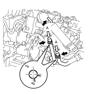
*a
View A
*b
Front Side
Connect the No. 2 oil cooler hose and No. 2 water by-pass hose to the EGR pipe with cooler sub-assembly, and slide the 2 clips to secure them.
Note:Engage the clip within the area shown in the illustration.
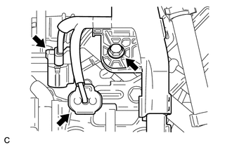
Connect the vacuum hose to the No. 2 EGR valve assembly.
Install the manifold absolute pressure sensor (diesel turbo pressure sensor) with the bolt and connect the vacuum transmitting hose.
9.0 N*m
92 kgf*cm
80 in.*lbf
-
Connect the 2 connectors and install the bolt.
8.0 N*m
82 kgf*cm
71 in.*lbf
Connect the connector and engage the wire harness clamp.
INSTALL EGR BYPASS VALVE SWITCHING VALVE (NO. 1 VACUUM SWITCHING VALVE ASSEMBLY)
ADD ENGINE COOLANT
INSPECT FOR COOLANT LEAK
INSPECT FOR EXHAUST GAS LEAK
INSTALL NO. 1 ENGINE COVER (w/ No. 1 Engine Cover)