SFI SYSTEM, Diagnostic DTC:P0451, P0452, P0453
| DTC Code | DTC Name |
|---|---|
| P0451 | Evaporative Emission Control System Pressure Sensor Range / Performance |
| P0452 | Evaporative Emission Control System Pressure Sensor / Switch Low Input |
| P0453 | Evaporative Emission Control System Pressure Sensor / Switch High Input |
DTC SUMMARY
| DTC No. | Monitoring Item | Malfunction Detection Condition | Trouble Area | Detection Timing | Detection Logic |
|---|---|---|---|---|---|
| P0451 | Difference between canister pressure sensor output value and manifold absolute pressure sensor output value | The difference between the canister pressure sensor output value and the manifold absolute pressure sensor output value with the ignition switch ON is large. |
|
Ignition switch off to ON | 2 trip |
| P0452 | Canister pressure sensor low input | EVAP pressure sensor less than 0.973 V for 1 second. |
|
1 trip | |
| P0453 | Canister pressure sensor high input | EVAP pressure sensor more than 4.095 V for 1 second. |
|
1 trip |
Tech Tips
The canister pressure sensor is built into the canister pump module.
DESCRIPTION
The description can be found in EVAP (Evaporative Emission) System Click here.
MONITOR DESCRIPTION
-
DTC P0451: Difference between canister pressure sensor output value and manifold absolute pressure sensor output value
If the difference between the atmospheric pressure calculated using the canister pressure sensor and that calculated using the MAP sensor exceeds the specified value, then the ECM determines there is a canister pressure sensor abnormality. The ECM then illuminates the MIL and stores the DTC (2 trip detection logic).
-
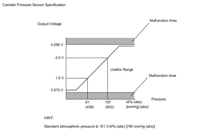
DTC P0452: Canister pressure sensor voltage low
If the canister pressure sensor voltage output (pressure) is below 0.973 V: 51.71 kPa(abs) [388 mmHg(abs)], the ECM interprets this as an open or short circuit in the canister pressure sensor or its circuit, and stops the EVAP system monitor. The ECM then illuminates the MIL and stores the DTC (1 trip detection logic).
-
DTC P0453: Canister pressure sensor voltage high
If the canister pressure sensor voltage output (pressure) is 4.095 V: 108.99 kPa(abs) [818 mmHg(abs)] or more, the ECM interprets this as an open or short circuit in the canister pressure sensor or its circuit, and stops the EVAP system monitor. The ECM then illuminates the MIL and stores the DTC (1 trip detection logic).
CONFIRMATION DRIVING PATTERN
-
Connect the GTS to the DLC3.
-
Turn the ignition switch to ON and turn the GTS on.
-
Enter the following menus: Powertrain / Engine / Data List / Intake Air.
-
Check that the intake air temperature is between 4.4 and 35°C (40 and 95°F).
-
Clear DTCs (even if no DTCs are stored, perform the clear DTC procedure) Click here.
-
Turn the ignition switch off and wait for at least 30 seconds.
-
Turn the ignition switch to ON and turn the GTS on.
-
Enter the following menus: Powertrain / Engine / Utility / All readiness.
-
Input the DTC: P0451, P0452 or P0453.
-
Check the DTC judgment result.
GTS Display Description NORMAL
-
DTC judgment completed
-
System normal
ABNORMAL
-
DTC judgment completed
-
System abnormal
INCOMPLETE
-
DTC judgment not completed
-
Perform driving pattern after confirming DTC enabling conditions
N/A
-
Unable to perform DTC judgment
-
Number of DTCs which do not fulfill DTC preconditions has reached ECU memory limit
Tech Tips
-
If the judgment result shows NORMAL, the system is normal.
-
If the judgment result shows ABNORMAL, the system has a malfunction.
-
-
If the judgment result is INCOMPLETE or N/A and no pending DTC is output, perform a universal trip and check for permanent DTCs Click here.
Tech Tips
-
If a permanent DTC is output, the system is malfunctioning.
-
If no permanent DTC is output, the system is normal.
-
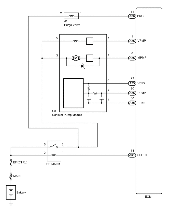
WIRING DIAGRAM
CAUTION / NOTICE / HINT
Note
-
When a vehicle is brought into the workshop, leave it as it is. Do not change the vehicle condition. For example, do not tighten the fuel cap.
-
Do not disassemble the canister pump module.
-
The GTS is required to conduct the following diagnostic troubleshooting procedure.
-
Inspect the fuses for circuits related to this system before performing the following inspection procedure.
PROCEDURE
-
CONFIRM DTC AND EVAP PRESSURE
-
Connect the GTS to the DLC3.
-
Turn the ignition switch to ON (do not start the engine).
-
Turn the GTS on.
-
Enter the following menus: Powertrain / Engine / Trouble Codes.
-
Read DTCs.
-
Enter the following menus: Powertrain / Engine / Data List / Vapor Pressure Pump.
-
Read the EVAP (Evaporative Emission) pressure displayed on the GTS.
Result Display (DTC Output) Test Result Suspected Trouble Area Proceed to P0451 -
-
Canister pressure sensor
-
Manifold absolute pressure sensor
C P0452 Below 51.71 kPa(abs) [388 mmHg(abs)]
-
Wire harness/connector (ECM - Canister pressure sensor)
-
Canister pressure sensor
-
Short in ECM circuit
A P0453 Higher than 108.99 kPa(abs) [818 mmHg(abs)]
-
Wire harness/connector (ECM - Canister pressure sensor)
-
Canister pressure sensor
-
Open in ECM circuit
B -
B 
CHECK HARNESS AND CONNECTOR (CANISTER PUMP MODULE - ECM) Click here
C
READ VALUE USING GTS (ATMOSPHERE PRESSURE) Click here
A 
-
-
CHECK HARNESS AND CONNECTOR (CANISTER PUMP MODULE - ECM)
-
Turn the ignition switch off.
-
Disconnect the ECM connector.
-
Measure the resistance according to the value(s) in the table below.
Result Tester Connection Condition Specified Condition Suspected Trouble Area Proceed to A35-20 (PPMP) - Body ground Always Below 10 Ω
-
Wire harness/connector (ECM - Canister pressure sensor)
-
Short in canister pressure sensor circuit
A 10 kΩ or higher
-
Wire harness/connector (ECM - Canister pressure sensor)
-
Short in ECM circuit
B -
B
READ VALUE USING GTS (ATMOSPHERE PRESSURE) Click here
A
-
-
CHECK HARNESS AND CONNECTOR (CANISTER PUMP MODULE - ECM)
-
Disconnect the canister pump module connector.
-
Disconnect the ECM connector.
-
Measure the resistance according to the value(s) in the table below.
Result Tester Connection Condition Specified Condition Suspected Trouble Area Proceed to A35-20 (PPMP) - Body ground Always 10 kΩ or higher Short in canister pressure sensor circuit A Below 10 Ω Short in wire harness/connector (ECM - Canister pressure sensor) B
A
REPAIR OR REPLACE HARNESS OR CONNECTOR (CANISTER PUMP MODULE - ECM) Click here
B
REPLACE ECM Click here
-
-
CHECK HARNESS AND CONNECTOR (CANISTER PUMP MODULE - ECM)
-
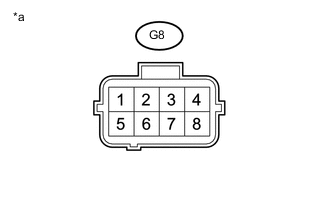
Text in Illustration *a Front view of wire harness connector
(to Canister Pump Module)
Disconnect the canister pump module connector.
-
Measure the resistance according to the value(s) in the table below.
Standard Resistance Tester Connection Condition Specified Condition G8-8 - Body ground Always 100 Ω or less -
Turn the ignition switch to ON.
-
Measure the voltage according to the value(s) in the table below.
Standard Voltage Tester Connection Switch Condition Specified Condition G8-6 - Body ground Ignition switch ON 4.5 to 5.5 V G8-7 - Body ground Ignition switch ON 4.5 to 5.5 V Result Test Result Suspected Trouble Area Proceed to Voltage and resistance within standard ranges Open in canister pressure sensor circuit A Voltage and/or resistance outside standard ranges Open in wire harness/connector (ECM - Canister pressure sensor) B
B
REPLACE ECM Click here
A
-
-
REPLACE CANISTER PUMP MODULE
-
Replace the canister pump module Click here.
NEXT
CHECK WHETHER DTC OUTPUT RECURS (AFTER REPAIR) Click here
-
-
REPAIR OR REPLACE HARNESS OR CONNECTOR (CANISTER PUMP MODULE - ECM)
NEXT
CHECK WHETHER DTC OUTPUT RECURS (AFTER REPAIR) Click here
-
REPLACE ECM
-
Replace the ECM Click here.
NEXT
CHECK WHETHER DTC OUTPUT RECURS (AFTER REPAIR) Click here
-
-
READ VALUE USING GTS (ATMOSPHERE PRESSURE)
-
Connect the GTS to the DLC3.
-
Turn the ignition switch to ON.
-
Turn the GTS on.
-
Enter the following menus: Powertrain / Engine / Data List / Atmosphere Pressure.
-
Compares Atmosphere Pressure displayed with the GTS to the actual atmosphere pressure.
Result Result Proceed to Difference with the actual atmosphere pressure is less than 4.7 kPa (abs) [36 mmHg (abs)]. A Difference with the actual atmosphere pressure is 4.7 kPa (abs) [36 mmHg (abs)] or more. B
B
REPLACE CANISTER PUMP MODULE Click here
A
-
-
READ VALUE USING GTS (MAP)
-
Connect the GTS to the DLC3.
-
Turn the ignition switch to ON.
-
Turn the GTS on.
-
Enter the following menus: Powertrain / Engine / Data List / MAP.
-
Compares the MAP displayed with the GTS to the actual atmosphere pressure.
Result Result Proceed to Difference with the actual atmosphere pressure is less than 4.7 kPa (abs) [36 mmHg (abs)]. A Difference with the actual atmosphere pressure is 4.7 kPa (abs) [36 mmHg (abs)] or more. B
A 
CHECK INTERMITTENT PROBLEMS Click here
B
REPLACE MANIFOLD ABSOLUTE PRESSURE SENSOR Click here
-
-
REPLACE CANISTER PUMP MODULE
-
Replace the canister pump module Click here.
NEXT
CHECK WHETHER DTC OUTPUT RECURS (AFTER REPAIR) Click here
-
-
REPLACE MANIFOLD ABSOLUTE PRESSURE SENSOR
-
Replace the manifold absolute pressure sensor Click here.
NEXT
-
-
CHECK WHETHER DTC OUTPUT RECURS (AFTER REPAIR)
-
Connect the GTS to the DLC3.
-
Turn the ignition switch to ON.
-
Turn the GTS on.
-
Clear the DTCs Click here.
-
Turn the ignition switch off and wait for at least 60 seconds.
-
Turn the ignition switch to ON.
-
Turn the GTS on.
-
Perform the Evaporative System Check using the GTS, referring to the Confirmation Driving Pattern.
-
Enter the following menus: Powertrain / Engine / Utility / All Readiness.
-
Input the DTC: P0451, P0452 or P0453.
-
Check the DTC judgment result.
Result GTS Display Description NORMAL
-
DTC judgment completed
-
System normal
ABNORMAL
-
DTC judgment completed
-
System abnormal
INCOMPLETE
-
DTC judgment not completed
-
Perform driving pattern after confirming DTC enabling conditions
N/A
-
Unable to perform DTC judgment
-
Number of DTCs which do not fulfill DTC preconditions has reached ECU memory limit
-
NEXT
END
-