HYBRID CONTROL SYSTEM, Diagnostic DTC:P2532-772
| DTC Code | DTC Name |
|---|---|
| P2532-772 | Ignition Switch Run Position Circuit High |
DESCRIPTION
The power source and HV CPU processors and their functions are integrated into the hybrid vehicle control ECU. The power source CPU and HV CPU use CAN communication to communicate with each other inside the hybrid vehicle control ECU. The power source CPU controls the opening and closing of the IG2 relay. The HV CPU detects that the IG2 relay is stuck ON (closed) based on relay operation information received from the power source CPU via CAN communication.
| DTC No. | INF Code | DTC Detection Condition | Trouble Area |
|---|---|---|---|
| P2532 | 772 | Voltage is still applied to IG2 terminal although an IG2 relay off command is received from the power source CPU. |
|
Tech Tips
If DTC P2532-772 is stored, the vehicle will turn off.
WIRING DIAGRAM
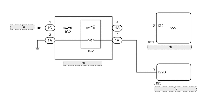
| *a | from Auxiliary Battery |
| *b | Hybrid Vehicle Control ECU |
| *c | No. 2 Integration Relay |
| *d | Certification ECU (Smart Key ECU Assembly) |
CAUTION / NOTICE / HINT
Tech Tips
After the repair, clear the DTCs and perform the following procedure to check that DTCs are not output.
-
Turn the power switch on (IG) and wait for 15 seconds or more.
-
Turn the power switch off and wait for 30 seconds or more.
PROCEDURE
-
CHECK DTC OUTPUT (HYBRID CONTROL)
-
Connect the GTS to the DLC3.
-
Turn the power switch on (IG).
-
Enter the following menus: Powertrain / Hybrid Control / Trouble Codes.
-
Check for DTCs.
Result Result Proceed to P2532-772 only is output. A DTCs except P2532-772 are output. B -
Turn the power switch off.
B 
CHECK FOR INTERMITTENT PROBLEMS Click here
A 
-
-
READ VALUE USING GTS (CAN BUS CHECK)
-
Connect the GTS to the DLC3.
-
Turn the power switch on (IG).
-
Enter the following menus: System Select / CAN Bus Check.
Result Result Proceed to All of the ECUs and sensors that are currently connected to the CAN communication system are displayed. A None of the ECUs and sensors that are currently connected to the CAN communication system are displayed, or some of them are not displayed.
(w/ Central Gateway ECU)
B None of the ECUs and sensors that are currently connected to the CAN communication system are displayed, or some of them are not displayed.
(w/o Central Gateway ECU)
C -
Turn the power switch off.
B 
GO TO CAN COMMUNICATION SYSTEM (w/ Central Gateway ECU) Click here
C
GO TO CAN COMMUNICATION SYSTEM (w/o Central Gateway ECU) Click here
A
-
-
CHECK HARNESS AND CONNECTOR (+B SHORT)
-

Text in Illustration *a Rear view of wire harness connector
(to Hybrid Vehicle Control ECU)
Disconnect the A21 hybrid vehicle control ECU connector.
-
Measure the voltage according to the value(s) in the table below.
Standard Voltage Tester Connection Condition Specified Condition A21-3 (IG2) - Body ground Power switch off 1 V or less -
Reconnect the A21 hybrid vehicle control ECU connector.
OK
REPLACE HYBRID VEHICLE CONTROL ECU Click here
NG
-
-
INSPECT NO. 2 INTEGRATION RELAY (IG2)
NG
REPLACE NO. 2 INTEGRATION RELAY Click here
OK
-
CHECK HARNESS AND CONNECTOR (HYBRID VEHICLE CONTROL ECU - NO. 2 INTEGRATION RELAY)
-
Disconnect the A21 hybrid vehicle control ECU connector.
-
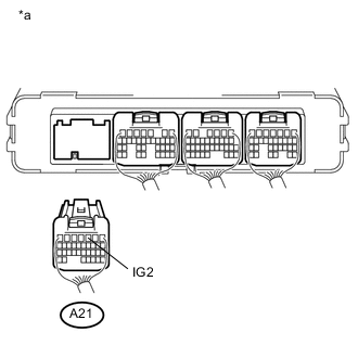
Text in Illustration *a Rear view of wire harness connector
(to Hybrid Vehicle Control ECU)
Remove the No. 2 integration relay from the engine room relay block and junction block assembly.
-
Measure the voltage according to the value(s) in the table below.
Standard Voltage Tester Connection Condition Specified Condition A21-3 (IG2) - Body ground Power switch off 1 V or less -
Install the No. 2 integration relay.
-
Reconnect the A21 hybrid vehicle control ECU connector.
NG
REPAIR OR REPLACE HARNESS OR CONNECTOR
OK
-
-
CHECK FOR INTERMITTENT PROBLEMS
-
Check for intermittent problems. Click here
-
Check the connection and terminal contact pressure of the connectors and wire harnesses between the hybrid vehicle control ECU and the engine room relay block and junction block assembly.
-
When the power switch is on (READY), jiggle the connectors and wire harnesses between the hybrid vehicle control ECU and the engine room relay block and junction block assembly.
Result Result Proceed to Problem symptom does not recur. A Problem symptom recurs. B -
A
REPLACE HYBRID VEHICLE CONTROL ECU Click here
B
REPAIR OR REPLACE MALFUNCTIONING PARTS, COMPONENT AND AREA
-