FRONT LOWER SUSPENSION ARM (for 4WD and Pre-Runner) INSTALLATION
Tech Tips
-
Use the same procedure for the RH and LH sides.
-
The procedure listed below is for the LH side.
-
INSTALL FRONT SPRING BUMPER
-
Install the front spring bumper to the vehicle.
- Torque:
- 31 N*m { 316 kgf*cm, 23 ft.*lbf }
-
-
INSTALL LOWER BALL JOINT ASSEMBLY
-
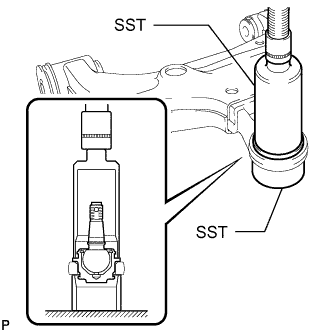
Using SST and press, press in a new lower ball joint.
- SST
- 09226-10010
- 09631-32020
-
Install a new snap ring.
Note
Make sure the snap ring is securely installed in the groove.
-
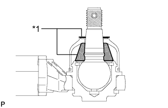
Text in Illustration *1 MP grease No. 2 Pack the upper ball joint with MP grease No. 2.
Grease capacity 8.0 g (0.282 oz.) -
Apply MP grease to the locations shown in the illustration.
Note
Do not apply MP grease No. 2 to the tapered or threaded parts of the ball joint.
-
Install a new dust cover to the lower arm.
-
Install a new dust cover set ring.
-
-
INSTALL FRONT NO. 2 LOWER ARM BUSH
-
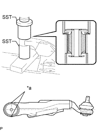
Text in Illustration *a Bush Positioning Protrusion Using SST and a press, install a new bush.
- SST
- 09710-20011 ( 09710-03081 )
- 09726-27012 ( 09726-02041 )
Note
Press the bush while making sure the bush positioning protrusions are perpendicular to the lower arm as shown in the illustration.
-
-
INSTALL FRONT NO. 1 LOWER ARM BUSH
-
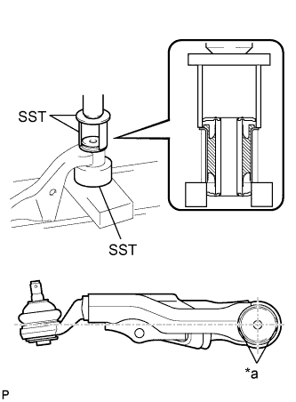
Text in Illustration *a Bush Positioning Protrusion Using SST and a press, press in a new bush.
- SST
- 09710-20011 ( 09710-06071 )
- 09710-22021 ( 09710-01071 )
Note
Press the bush while making sure the bush positioning protrusions are perpendicular to the lower arm as shown in the illustration.
-
-
INSTALL FRONT LOWER BALL JOINT ATTACHMENT
-
Install the ball joint attachment with the nut and a new cotter pin.
- Torque:
- 140 N*m { 1428 kgf*cm, 103 ft.*lbf }
-
-
TEMPORARILY INSTALL FRONT LOWER SUSPENSION ARM SUB-ASSEMBLY LH
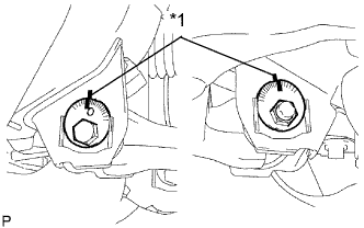
Text in Illustration *1 Matchmark
-
Temporarily install the lower arm, and No. 1 and No. 2 camber adjusting cams with the 2 camber adjusting cams and 2 nuts.
-
Align the matchmarks on the No. 1 camber adjusting cam and No. 2 camber adjusting cam with the corresponding matchmarks on the vehicle frame.
-
Install the ball joint attachment with the 2 bolts.
- Torque:
- 160 N*m { 1632 kgf*cm, 118 ft.*lbf }
-
-
TEMPORARILY INSTALL FRONT SHOCK ABSORBER WITH COIL SPRING
-
Temporarily install the shock absorber with coil spring with the bolt and nut.
-
-
INSTALL FRONT WHEEL
- Torque:
- 105 N*m { 1,071 kgf*cm, 77 ft.*lbf }
-
STABILIZE SUSPENSION
-
Lower the vehicle.
-
Press down on the vehicle several times to stabilize the suspension.
-
-
TIGHTEN FRONT LOWER SUSPENSION ARM SUB-ASSEMBLY LH
-
Tighten the 2 nuts.
- Torque:
- 140 N*m { 1428 kgf*cm, 103 ft.*lbf }
-
-
TIGHTEN FRONT SHOCK ABSORBER WITH COIL SPRING
-
Fix the nut in place and tighten the bolt.
- Torque:
- 95 N*m { 969 kgf*cm, 70 ft.*lbf }
Note
Do not tighten the nut.
-
-
INSPECT AND ADJUST FRONT WHEEL ALIGNMENT