SFI SYSTEM(w/o Canister Pump Module), Diagnostic DTC:P2AB711, P2ABA11
| DTC Code | DTC Name |
|---|---|
| P2AB711 | Wastegate Position Sensor "A" Circuit Short to Ground |
| P2ABA11 | Wastegate Position Sensor "B" Circuit Short to Ground |
DESCRIPTION
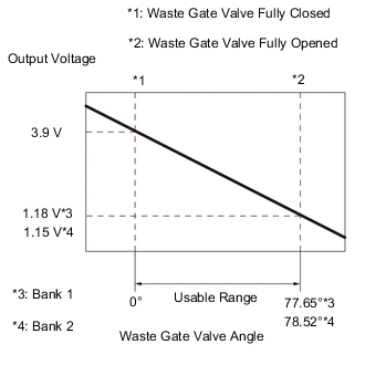
The waste gate valve position sensor is installed to the waste gate valve output gear and detects the waste gate valve position. The waste gate valve position sensor is a non-contact type and uses Hall elements which can yield the magnetic field strength as an electrical signal through the Hall effect, which enables output voltage corresponding to the waste gate valve position to be obtained linearly.
| DTC No. | Detection Item | DTC Detection Condition | Trouble Area | MIL | Memory | Note |
|---|---|---|---|---|---|---|
| P2AB711 | Wastegate Position Sensor "A" Circuit Short to Ground | The waste gate valve position sensor (bank 1) output voltage is less than 0.2 V for 3 seconds or more (1 trip detection logic). |
|
- | DTC stored | SAE: P2AB8 |
| P2ABA11 | Wastegate Position Sensor "B" Circuit Short to Ground | The waste gate valve position sensor (bank 2) output voltage is less than 0.2 V for 3 seconds or more (1 trip detection logic). |
|
- | DTC stored | SAE: P2ABB |
MONITOR DESCRIPTION
The ECM uses the waste gate valve position sensor to monitor the waste gate valve opening angle. If the waste gate valve position sensor output voltage is less than 0.2 V for 0.3 seconds or more, the ECM will store this DTC.
MONITOR STRATEGY
| Frequency of Operation | Continuous |
CONFIRMATION DRIVING PATTERN
-
Connect the GTS to the DLC3.
-
Turn the engine switch on (IG).
-
Turn the GTS on.
-
Clear the DTCs (even if no DTCs are stored, perform the clear DTC procedure).
-
Start the engine and warm it up until the engine coolant temperature reaches 75°C (167°F) or higher.
-
Turn the engine switch off and wait for at least 30 seconds.
-
Turn the engine switch on (IG).
-
Turn the GTS on.
-
Start the engine.
-
Idle the engine for 5 seconds or more.
-
Enter the following menus: Powertrain / Engine / Trouble Codes.
-
Read the DTCs.
Tech Tips
-
If a pending DTC is output, the system is malfunctioning.
-
If a pending DTC is not output, perform the following procedure.
-
-
Enter the following menus: Powertrain / Engine / Utility / All Readiness.
-
Input the DTC: P2AB711 or P2ABA11.
-
Check the DTC judgment result.
GTS Display Description NORMAL
-
DTC judgment completed
-
System normal
ABNORMAL
-
DTC judgment completed
-
System abnormal
INCOMPLETE
-
DTC judgment not completed
-
Perform driving pattern after confirming DTC enabling conditions
Tech Tips
-
If the judgment result is NORMAL, the system is normal.
-
If the judgment result is ABNORMAL, the system is malfunctioning.
-
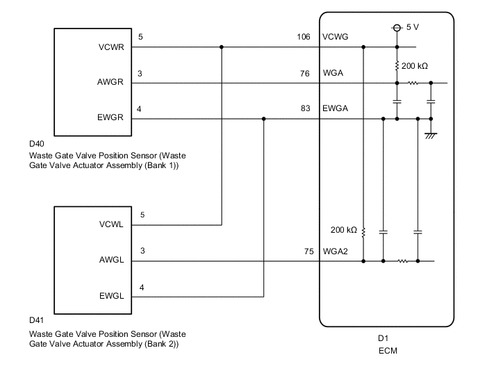
WIRING DIAGRAM
CAUTION / NOTICE / HINT
Tech Tips
-
Read Freeze Frame Data using the GTS. The ECM records vehicle and driving condition information as Freeze Frame Data the moment a DTC is stored. When troubleshooting, Freeze Frame Data can help determine if the vehicle was moving or stationary, if the engine was warmed up or not, if the air fuel ratio was lean or rich, and other data from the time the malfunction occurred.
-
Bank 1 refers to the bank that includes the No. 1 cylinder*.
*: The No. 1 cylinder is the cylinder which is farthest from the transmission.
-
Bank 2 refers to the bank that does not include the No. 1 cylinder.
DTC Suspected Area P2AB711 Bank 1 P2ABA11 Bank 2
PROCEDURE
-
CHECK HARNESS AND CONNECTOR
Tech Tips
Make sure that the connector is properly connected. If it is not, securely connect it and check for DTCs again.
-
Disconnect the waste gate valve actuator assembly (turbocharger sub-assembly) connector.
-
Turn the engine switch on (IG).
-
Measure the voltage according to the value(s) in the table below.
Standard Voltage Tester Connection Condition Specified Condition D40-5 (VCWR) - Body ground Engine switch on (IG) 4.5 to 5.5 V D41-5 (VCWL) - Body ground Engine switch on (IG) 4.5 to 5.5 V D40-3 (AWGR) - Body ground Engine switch on (IG) 4.5 to 5.5 V D41-3 (AWGL) - Body ground Engine switch on (IG) 4.5 to 5.5 V -
Turn the engine switch off and wait for at least 30 seconds.
-
Measure the resistance according to the value(s) in the table below.
Standard Resistance Tester Connection Condition Specified Condition D40-5 (VCWR) - D40-3 (AWGR) Engine switch off 190 to 210 kΩ D41-5 (VCWL) - D41-3 (AWGL) Engine switch off 190 to 210 kΩ Result Proceed to OK NG Tech Tips
Perform "Inspection After Repair" after replacing the turbocharger sub-assembly.
OK 
REPLACE WASTE GATE VALVE ACTUATOR ASSEMBLY (TURBOCHARGER SUB-ASSEMBLY) Click here
NG 
-
-
CHECK HARNESS AND CONNECTOR (WASTE GATE VALVE ACTUATOR ASSEMBLY (TURBOCHARGER SUB-ASSEMBLY) - ECM)
-
Disconnect the waste gate valve actuator assembly (turbocharger sub-assembly) connector.
-
Disconnect the ECM connector.
-
Measure the resistance according to the value(s) in the table below.
Standard Resistance Tester Connection Condition Specified Condition D40-5 (VCWR) - D1-106 (VCWG) Always Below 1 Ω D41-5 (VCWL) - D1-106 (VCWG) Always Below 1 Ω D40-3 (AWGR) or D1-76 (WGA) - Body ground and other terminals Always 10 kΩ or higher D41-3 (AWGL) or D1-75 (WGA2) - Body ground and other terminals Always 10 kΩ or higher Result Proceed to OK NG
OK
REPLACE ECM Click here
NG
REPAIR OR REPLACE HARNESS OR CONNECTOR
-