МАСЛЯНЫЙ НАСОС УСТАНОВКА

-
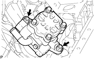
INSTALL TIMING GEAR CASE ASSEMBLY
-
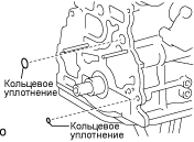
Install 2 new O-rings to the cylinder block grooves.
-
Install the stud bolt.
- Torque:
- 8.0 N*m { 82 kgf*cm, 71 in.*lbf }
-
Remove any old packing (FIPG) material.
-
Install the oil pump rotor to the timing gear case.
-
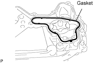
Install a new gasket to the groove of the timing gear case.
-
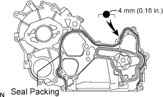
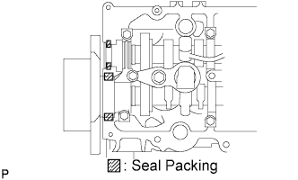
Apply seal packing to the timing gear case as shown in the illustration.
Seal packing Toyota Genuine Seal Packing Black, Three Bond 1207B or equivalent Seal width 4 mm (0.16 in.) Note
After applying FIPG, install the timing gear case assembly within 3 minutes and then tighten its bolts within 15 minutes.
-
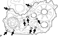
Install the timing gear case with the union bolt and 8 bolts.
- Torque:
- 16 N*m { 163 kgf*cm, 12 ft.*lbf }
- 13 N*m { 133 kgf*cm, 10 ft.*lbf }
-
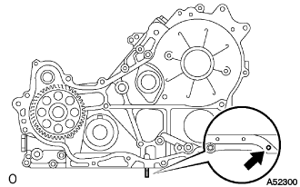
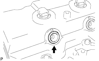
Remove the screw plug.
-
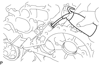
Pour approximately 50 cc (1.7 fl.oz) of engine oil into the oil pump.
-
Reinstall a new gasket and the screw plug.
- Torque:
- 42 N*m { 423 kgf*cm, 31 ft.*lbf }
-
-
INSTALL OIL STRAINER SUB-ASSEMBLY
-
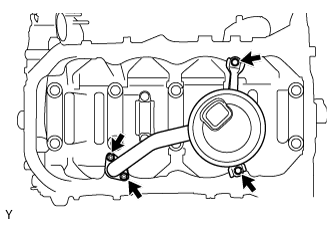
Install a new gasket and the oil strainer with the 2 bolts and 2 nuts.
- Torque:
- 8.0 N*m { 82 kgf*cm, 71 in.*lbf }
-
-
INSTALL OIL PAN SUB-ASSEMBLY
-
Remove any old packing (FIPG) material.
-
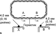
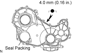
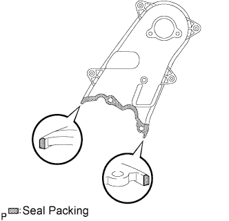
Apply seal packing to the oil pan as shown in the illustration.
Seal packing Toyota Genuine Seal Packing Black, Three Bond 1207B or equivalent Seal width 4.0 mm (0.16 in.) Note
Install the oil pan assembly within 3 minutes and tighten its bolts within 15 minutes after applying FIPG is competed.
-
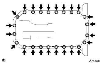
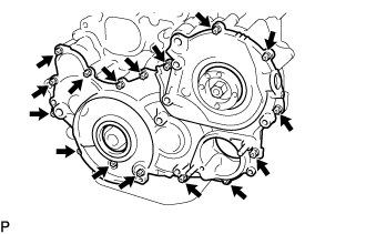
Install the oil pan with the 22 bolts and 2 nuts.
- Torque:
- 16 N*m { 163 kgf*cm, 12 ft.*lbf }
-
Install a new gasket and the drain plug.
- Torque:
- 34 N*m { 347 kgf*cm, 25 ft.*lbf }
-
-
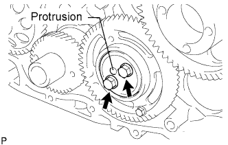
INSTALL SUPPLY PUMP GEAR
-
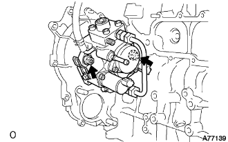
Install the supply pump with the 2 nuts.
- Torque:
- 21 N*m { 214 kgf*cm, 15 ft.*lbf }
-
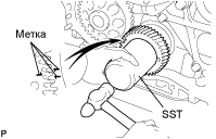
Temporarily install the O-ring and supply pump gear with the nut.
Tech Tips
Fit the key (protrusion) of the supply pump to the key slot of the supply pump gear.
-
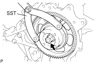
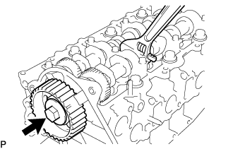
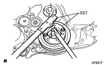
Using SST, tighten the nut.
- SST
- 09960-10010 ( 09962-01000, 09963-01000 )
- Torque:
- 64 N*m { 653 kgf*cm, 47 ft.*lbf }
-
-
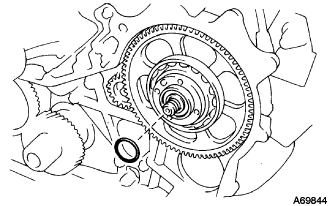
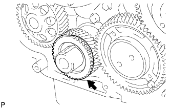
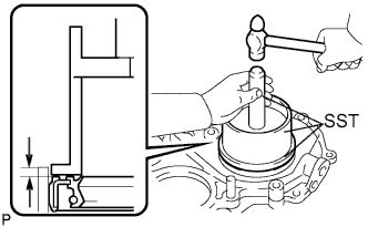
INSTALL CRANKSHAFT TIMING GEAR
-
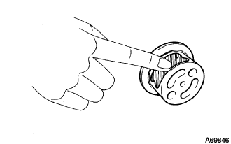
Face the crankshaft timing gear with timing mark 1 facing forward.
-
Align the set key on the crankshaft with the key groove of the crankshaft timing gear.
-
Using SST and a hammer, tap in the timing gear.
- SST
- 09223-00010
-
-
INSTALL IDLE GEAR SHAFT NO.1
-
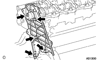
Coat the idle gear shaft No.1 with engine oil as shown in the illustration.
-
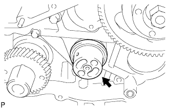
Install the gear shaft.
-
-
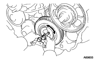
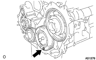
INSTALL IDLE GEAR NO.1
-
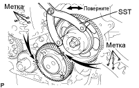
Align the "5" timing marks of the idle gear and crankshaft timing gear.
-
Using SST, turn the supply pump gear, and align the "4" timing marks of the idle gear and supply pump gear, and mesh the gears.
- SST
- 09960-10010 ( 09962-01000, 09963-00600 )
-
-
INSTALL CRANKSHAFT POSITION SENSOR PLATE NO.1
-
Align the set key with the key groove of the sensor plate.
-
Install the sensor plate with the cup side facing outward.
-
-
INSTALL IDLE GEAR THRUST PLATE
-
Face the thrust plate with the protrusion facing outward.
-
Align the bolt holes, and install the thrust plate with the 2 bolts.
- Torque:
- 50 N*m { 510 kgf*cm, 37 ft.*lbf }
-
-
INSTALL TIMING CHAIN OR BELT COVER OIL SEAL
-
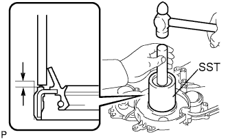
Using SST and a hammer, tap in a new oil seal until its surface is flush with the timing gear cover edge.
- SST
- 09649-17010
- 09950-70010 ( 09951-07100 )
Oil seal depth from the flat-end surface 0 to -0.5 mm (0 to -0.020 in.) -
Apply MP grease to the oil seal lip.
Note
Keep the lip clean. Prevent dirt and dust from adhering to that area.
-
-
INSTALL TIMING GEAR CASE OR TIMING CHAIN CASE OIL SEAL
-
Using SST and a hammer, tap in a new oil seal until its surface is flush with the timing gear cover edge.
- SST
- 09608-32010
- 09950-70010 ( 09951-07100 )
Oil seal depth from the flat-end surface 0 to -0.5 mm (0 to -0.020 in.) -
Apply MP grease to the oil seal lip.
Note
Keep the lip clean. Prevent dirt and dust from adhering to that area.
-
-
INSTALL TIMING GEAR CASE
-
Remove the service bolt.
-
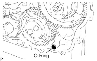
Install a new O-ring to the timing gear case assembly.
-
Apply seal packing to the timing gear case as shown in the illustration.
Seal packing Toyota Genuine Seal Packing Black, Three Bond 1207B or equivalent Seal width 4.0 mm (0.16 in.) Note
Install the timing gear case within 3 minutes and tighten its bolts within 15 minutes after applying FIPG is competed.
-
Install the timing gear case with the 14 bolts and 2 nuts.
- Torque:
- 13 N*m { 133 kgf*cm, 10 ft.*lbf }
-
-
INSTALL WATER PUMP ASSEMBLY
-
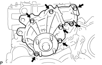
Install a new gasket and the water pump with the 5 bolts and 2 nuts.
- Torque:
- 13 N*m { 133 kgf*cm, 10 ft.*lbf }
-
-
INSTALL TIMING BELT COVER NO.2
-
Apply seal packing to the timing gear cover as shown in the illustration.
Seal packing Toyota Genuine Seal Packing Black, Three Bond 1207B or equivalent Note
Install the timing belt No. 2 cover within 3 minutes and tighten its bolts and nut within 15 minutes after applying FIPG is competed.
-
Install the timing belt No. 2 cover with the 4 bolts and nut.
- Torque:
- 10 N*m { 102 kgf*cm, 7 ft.*lbf }
-
-
INSTALL CAMSHAFT TIMING PULLEY
-
Install the set key to the key groove of the camshaft.
-
Align the set key with the key groove of the timing pulley.
-
Hold the hexagon portion of the camshaft, and install the timing pulley with the bolt.
- Torque:
- 98 N*m { 1,000 kgf*cm, 72 ft.*lbf }
-
-
INSTALL CYLINDER HEAD COVER SUB-ASSEMBLY
-
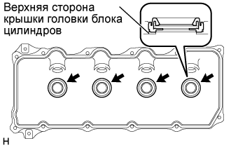
Install 4 new No. 3 cylinder head cover gaskets to the cylinder head cover as shown in the illustration.
Note
-
Do not install the gaskets at an angle.
-
Keep the lip of the gasket free from foreign materials.
-
-
Install a new cylinder head cover gasket to the cylinder head cover.
-
Apply seal packing to the cylinder head as shown in the illustration.
Seal packing Toyota Genuine Seal Packing Black, Three Bond 1207B or equivalent Note
After applying the seal packing, parts must be assembled within 3 minutes, and then tighten them within 15 minutes.
-
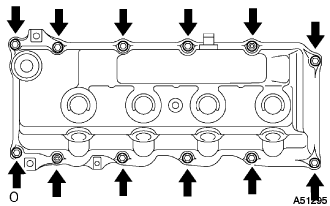
Install the cylinder head cover with 10 bolts and 2 nuts. Uniformly tighten the bolts and nuts in several steps.
- Torque:
- 9.0 N*m { 92 kgf*cm, 80 in.*lbf }
-
-
INSTALL NOZZLE HOLDER SEAL
-
Install 4 new holder seals.
-
-
INSTALL OIL FILLER CAP SUB-ASSEMBLY
-
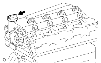
Install the oil filler cap.
-
-
INSTALL ENGINE OIL LEVEL SENSOR
-
Установите новую прокладку, затем установите датчик уровня моторного масла и закрепите его 4 болтами.
- Torque:
- 7,0 Н*м { 71 кгс*см, 52 фунт-сила-дюйма }
-
-
INSTALL CRANKSHAFT POSITION SENSOR
-
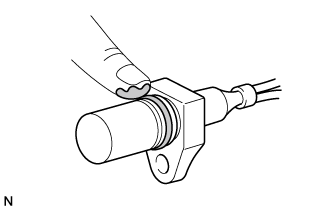
Apply a light coat of engine oil to the O-ring of the crankshaft position sensor.
-
Install the crankshaft position sensor with the bolt.
- Torque:
- 8.5 N*m { 87 kgf*cm, 75 in.*lbf }
Note
Be careful that the O-ring is not cracked or jammed when installing the crankshaft position sensor.
-
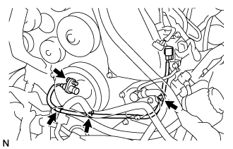
Connect the 3 wire harness clamps.
-
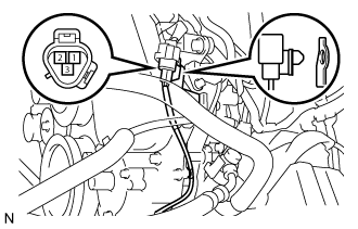
Connect the crankshaft position sensor connector to the vacuum pipe No.1.
-
Connect the crankshaft position sensor connector.
-
-
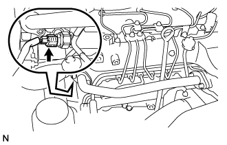
INSTALL CAMSHAFT POSITION SENSOR
-
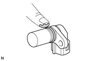
Apply a light coat of engine oil to the O-ring of the camshaft position sensor.
-
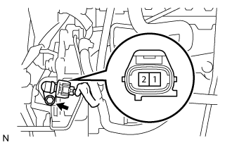
Install the camshaft position sensor with the bolt.
- Torque:
- 8.5 N*m { 87 kgf*cm, 75 in.*lbf }
Note
Be careful that the O-ring is not cracked or jammed when installing the camshaft position sensor.
-
Connect the camshaft position sensor connector.
-
-
INSTALL VACUUM PUMP ASSEMBLY
-
Нанесите на 2 новых кольцевых уплотнения моторное масло.
-
Установите 2 кольцевых уплотнения на вакуумный насос в сборе.
-
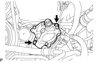
Закрепите вакуумный насос в сборе на двигателе 2 гайками.
- Torque:
- 21 Н*м { 210 кгс*см, 15 фунт-сила-футов }
Note
-
Не допускайте падения уплотнения вакуумного насоса.
-
Убедитесь, что вакуумный насос в сборе установлен надежно.
-
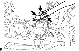
Закрепите 2 новые прокладки и штуцер вакуумного насоса с помощью пустотелого соединительного болта-штуцера.
- Torque:
- 14 Н*м { 140 кгс*см, 10 фунт-сила-футов }
Note
Убедитесь, что стопор штуцера вакуумного насоса надежно закреплен на вакуумном насосе в сборе.
-
Подсоедините 2 шланга к вакуумному насосу и закрепите их фиксатором.
Note
Расположите вакуумный шланг таким образом, чтобы белая метка была сверху.
-
-
INSTALL CRANKSHAFT PULLEY
-
Затяните болт, удерживая шкив коленчатого вала с помощью SST.
- SST
- 09213-58013
- 09330-00021
- Torque:
- 365 Н*м { 3 722 кгс*см, 270 фунт-сила-футов }
-
-
INSTALL TIMING BELT IDLER SUB-ASSEMBLY NO.1.
-
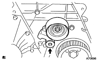
С помощью шестигранной головки на 10 мм закрепите новую шайбу и опорный ролик приводного ремня газораспределения болтом.
- Torque:
- 35 Н*м { 357 кгс*см, 26 фунт-сила-футов }
Note
Запрещается использовать шайбу повторно.
-
-
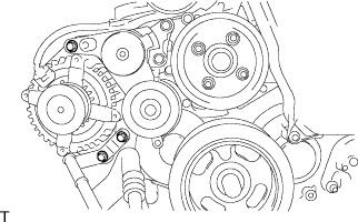
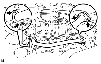
INSTALL V-RIBBED BELT TENSIONER ASSEMBLY
-
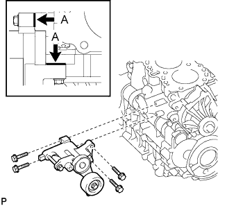
Временно установите натяжитель поликлинового ремня и закрепите его 4 болтами.
Tech Tips
Убедитесь, что натяжитель поликлинового ремня касается блока цилиндров в точках A, показанных на рисунке.
-
Закрепите натяжитель поликлинового ремня 4 болтами.
- Torque:
- 21 Н*м { 214 кгс*см, 15 фунт-сила-футов }
-
-
INSTALL GENERATOR ASSEMBLY
-
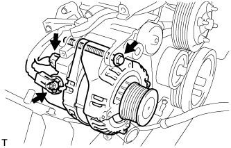
Install the generator assembly with the bolt.
- Torque:
- 62 N*m { 632 kgf*cm, 46 ft.*lbf }
-
Install the generator wire to terminal B with the nut.
- Torque:
- 9.8 N*m { 100 kgf*cm, 87 in.*lbf }
-
Install the terminal cap.
-
Connect the generator connector.
-
-
INSTALL GENERATOR BRACKET
-
Install the generator bracket with the 2 bolts.
- Torque:
- 36 N*m { 367 kgf*cm, 27 ft.*lbf }
-
-
INSTALL IDLE PULLEY ASSEMBLY
-
Установите опорный ролик и шайбы и закрепите их болтом.
- Torque:
- 45 Н*м { 459 кгс*см, 33 фунт-сила-фута }
-
-
INSTALL COMPRESSOR BRACKET
-
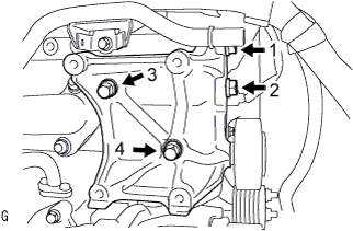
Временно установите кронштейн компрессора и закрепите его 4 болтами.
Tech Tips
Убедитесь, что кронштейн компрессора касается блока цилиндров.
-
Установите кронштейн компрессора, затянув 4 болта, как показано на рисунке.
- Torque:
- 45 Н*м { 459 кгс*см, 33 фунт-сила-фута }
-
-
INSTALL PUMP DRIVE SHAFT PULLEY
-
CHECK PUMP DRIVE SHAFT THRUST CLEARANCE
-
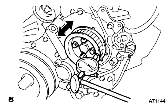
Push the pump drive shaft pulley back and forth to check a thrust clearance of the injection pump drive shaft.
Thrust clearance 0.15 to 0.55 mm (0.0059 to 0.0217 in.) Note
Make sure that the crankshaft pulley's notch is at 30 degree in the counterclockwise direction form the TDC position.
Tech Tips
If there is not thrust clearance, disassemble and reassemble the injection pump and pump drive shaft pulley.
-
-
INSTALL COMMON RAIL ASSEMBLY
-
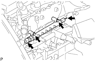
Install the common rail assembly with the 2 bolts.
- Torque:
- 38 N*m { 387 kgf*cm, 28 ft.*lbf }
-
Connect the fuel hose to the fuel pressure limiter.
-
Connect the fuel pressure sensor connector.
-
-
INSTALL FUEL INLET PIPE SUB-ASSEMBLY
Note
-
When replacing the fuel supply pump, common rail, cylinder block, cylinder head, cylinder head gasket, or timing gear case with a new one, replace the fuel inlet pipe.
-
Be careful not to adhere dusts, dirt or any other materials onto the joint area of the fuel inlet pipe.
-
Temporarily install the fuel inlet pipe.
-
Using SST, tighten the injection pipe on the common rail side.
- SST
- 09023-12701
- Torque:
- 32 N*m { 326 kgf*cm, 24 ft.*lbf, for use with SST }
-
Using SST, tighten the injection pipe on the supply pump side.
- SST
- 09023-12701
- Torque:
- 32 N*m { 326 kgf*cm, 24 ft.*lbf, for use with SST }
-
-
INSTALL INJECTION PIPE
- SST
- 09023-12701
Note
-
When replacing the fuel injector, common rail, or cylinder head with a new one, replace injection pipes No. 1, No. 2, No. 3, and No. 4.
-
Keep clean the joint of the injection pipe.
-
Install the injection pipes.
-
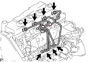
Temporarily install the 4 injection pipes.
-
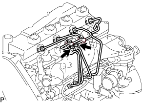
Install the injection pipe clamp No.3 in 2 nuts.
- Torque:
- 5.0 N*m { 51 kgf*cm, 44 in.*lbf }
-
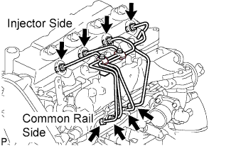
Fasten the union sequentially, from the injection pipe common rail to the injector, using SST.
- SST
- 09023-12701
- Torque:
- Use union nut wrench and torque wrench
- 32 N*m { 326 kgf*cm, 24 ft.*lbf }
-
-
INSTALL OIL LEVEL GAGE GUIDE
-
Установите на трубку щупа проверки уровня масла новое уплотнительное кольцо.
-
Нанесите на уплотнительное кольцо тонкий слой моторного масла.
-
Установите трубку щупа проверки уровня масла и закрепите ее болтом.
- Torque:
- 8,0 Н*м { 82 кгс*см, 71 фунт-сила-дюйм }
-
Установите щуп проверки уровня масла.
-
-
INSTALL EGR PIPE SUB-ASSEMBLY NO.1
-
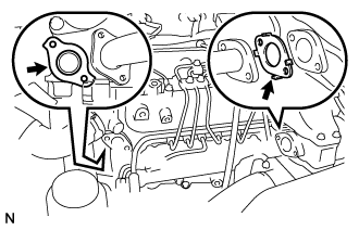
Install 2 new gaskets to the cylinder head and the EGR pipe sub-assembly No.1 as shown in the illustration.
-
Install the EGR pipe with the 2 bolts and the 2 nuts.
- Torque:
- 13 N*m { 133 kgf*cm, 10 ft.*lbf }
-
Connect the fuel pressure sensor connector.
-
-
INSTALL FAN PULLEY
-
Установите шкив вентилятора и закрепите его 4 гайками.
- Torque:
- 23 Н*м { 235 кгс*см, 17 фунт-сила-футов }
-
-
PERFORM PISTON AND VALVE BREAK PREVENT WORK
-
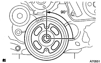
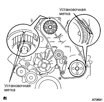
При повороте распредвала со снятым приводным ремнем газораспределения поверните коленчатый вал на 90° против часовой стрелки.
Note
При установке приводного ремня газораспределения поверните распредвал, чтобы совместить синхронизирующие метки, а затем поверните коленчатый вал по часовой стрелке и совместите синхронизирующие метки, как показано на рисунке.
-
-
INSTALL TIMING BELT
-
Удостоверьтесь, что установочные метки совмещены, как показано на рисунке.
-
Установите приводной ремень газораспределения на шкив приводного вала насоса, зубчатое колесо распредвала и опорный ролик приводного ремня газораспределения № 1, придерживаясь этой последовательности.
-
Установите натяжитель вертикально на пресс.
Note
-
Не допускайте царапания и деформирования конца толкателя.
-
Запрессуйте толкатель натяжителя.
-
Обеспечьте защиту конца толкателя от повреждений ветошью.
-
-
С помощью пресса медленно запрессуйте толкатель с усилием 981 - 9807 Н (100 - 1000 кгс, 220 - 2205 фунт-силы).
Note
Не прикладывайте к толкателю усилие свыше 981 - 9807 Н (100 - 1000 кгс, 220 - 2205 фунт-силы).
-
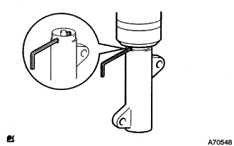
Совместите отверстия в толкателе и кожухе. Для сохранения положения установки толкателя пропустите через отверстия шестигранную головку на 1,27 мм.
-
Временно закрепите натяжитель приводного ремня 2 болтами, прижимая опорный ролик к приводному ремню газораспределения.
-
Затяните 2 болта.
- Torque:
- 13 Н*м { 133 кгс*см, 10 фунт-сила-футов }
Note
Равномерно затяните 2 болта и установите натяжитель
-
Выньте из натяжителя торцевой гаечный ключ на 1,5 мм.
-
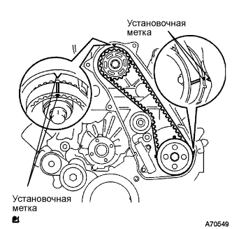
Поверните коленчатый вал по часовой стрелке на два оборота и убедитесь, что установочные метки совмещены, как показано на рисунке.
-
-
INSTALL TIMING BELT COVER NO.1
-
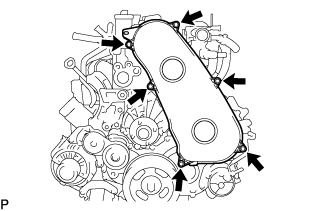
Установите крышку приводного ремня газораспределения № 1 и закрепите ее 6 болтами.
- Torque:
- 6,0 Н*м { 61 кгс*см, 53 фунт-сила-дюйма }
-
Присоедините зажим жгута проводов.
-
-
INSTALL VANE PUMP ASSEMBLY
-
Установите новое кольцевое уплотнение лопастного насоса на лопастной насос в сборе.
-
Закрепите лопастной насос в сборе 2 гайками.
- Torque:
- 39 Н*м { 398 кгс*см, 29 фунт-сила-футов }
Note
Убедитесь, что кольцевое уплотнение лопастного насоса не зажато между другими деталями.
-
-
INSTALL ENGINE ASSEMBLY