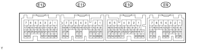
SFI SYSTEM TERMINALS OF ECM
Tech Tips
Each ECM terminal's standard normal voltage is shown in the table below.
In the table, first check the information under "Condition". Look under "Symbols (Terminal No.)" for the terminals to be inspected. The standard voltage between the terminals is shown under "Specified Condition".
Use the illustration above as a reference for the ECM terminals.
| Symbols (Terminal No.) | Wiring Color | Terminal Description | Condition | Specified Condition |
|---|---|---|---|---|
| BATT (E9-3) - E1 (E12-3) | L - BR | Battery (for measuring battery voltage and for ECM memory) | Always | 9 to 14 V |
| +BM (E9-7) - E1 (E12-3) | R-W - BR | Power source of throttle motor | Always | 9 to 14 V |
| IGSW (E9-9) - E1 (E12-3) | B-O - BR | Ignition switch | Ignition switch ON | 9 to 14 V |
| +B (E9-1) - E1 (E12-3) | B - BR | Power source of ECM | Ignition switch ON | 9 to 14 V |
| MREL (E9-8) - E1 (E12-3) | W-G - BR | EFI relay | Ignition switch ON | 9 to 14 V |
| VC (E12-18) - E2 (E12-28) | LG-B - BR | Power source of sensor (specific voltage) | Ignition switch ON | 4.5 to 5.5 V |
| VTA1 (E12-20) - E2 (E12-28) | B-R - BR | Throttle position sensor (for engine control) | Ignition switch ON, accelerator pedal fully released | 0.5 to 1.1 V |
| VTA1 (E12-20) - E2 (E12-28) | B-R - BR | Throttle position sensor (for engine control) | Ignition switch ON, accelerator pedal fully depressed | 3.2 to 4.8 V |
| VTA2 (E12-19) - E2 (E12-28) | LG - BR | Throttle position sensor (for sensor malfunction detection) | Ignition switch ON, accelerator pedal fully released | 2.1 to 3.1 V |
| VTA2 (E12-19) - E2 (E12-28) | LG - BR | Throttle position sensor (for sensor malfunction detection) | Ignition switch ON, accelerator pedal fully depressed | 4.5 to 5.5 V |
| VPA (E9-18) - EPA (E9- 20) | W-L - BR-W | Accelerator pedal position sensor (for engine control) | Ignition switch ON, accelerator pedal fully released | 0.5 to 1.1 V |
| VPA (E9-18) - EPA (E9- 20) | W-L - BR-W | Accelerator pedal position sensor (for engine control) | Ignition switch ON, accelerator pedal fully depressed | 2.5 to 4.6 V |
| VPA2 (E9-19) - EPA2 (E9-21) | GR-G - BR-Y | Accelerator pedal position sensor (for sensor malfunction detection) | Ignition switch ON, accelerator pedal fully released | 1.5 to 2.9 V |
| VPA2 (E9-19) - EPA2 (E9-21) | GR-G - BR-Y | Accelerator pedal position sensor (for sensor malfunction detection) | Ignition switch ON, accelerator pedal fully depressed | 3.5 to 5.5 V |
| VCPA (E9-26) - EPA (E9-20) | LG-R - BR-W | Power source of accelerator pedal position sensor (for VPA) | Ignition switch ON | 4.5 to 5.5 V |
| VCP2 (E9-27) - EPA2 (E9-21) | BR-R - BR-Y | Power source of accelerator pedal position sensor (for VPA2) | Ignition switch ON | 4.5 to 5.5 V |
| VG (E11-28) - E2G (E11-30) | L-W - L-R | MAF meter | Idling, shift position on P or N (for A/T) or neutral (for M/T), A/C switch off | 0.5 to 3.0 V |
| THA (E11-29) - E2 (E12-28) | L-B - BR | IAT sensor | Idling, intake air temperature 20°C (68°F) | 0.5 to 3.4 V |
| THW (E12-32) - E2 (E12-28) | B - BR | ECT sensor | Idling, engine coolant temperature 80°C (176°F) | 0.2 to 1.0 V |
| #10 (E11-6) - E01 (E12-7) #20 (E11-5) - E01 (E12-7) #30 (E11-2) - E01 (E12-7) #40 (E11-1) - E01 (E12-7) |
L - W-B G - W-B R - W-B W - W-B |
Injector | Ignition switch ON | 9 to 14 V |
| #10 (E11-6) - E01 (E12-7) #20 (E11-5) - E01 (E12-7) #30 (E11-2) - E01 (E12-7) #40 (E11-1) - E01 (E12-7) |
L - W-B G - W-B R - W-B W - W-B |
Injector | Idling | Pulse generation (see waveform 6) |
| IGT1 (E12-17) - E1 (E12-3) IGT2 (E12-16) - E1 (E12-3) IGT3 (E12-15) - E1 (E12-3) IGT4 (E12-14) - E1 (E12-3) |
R - BR R-L - BR G-B - BR G - BR |
Ignition coil with igniter ignition signal | Idling | Pulse generation (see waveform 5) |
| IGF1 (E12-23) - E1 (E12-3) | G-R - BR | Ignition coil with igniter (ignition confirmation signal) | Ignition switch ON | 4.5 to 5.5 V |
| IGF1 (E12-23) - E1 (E12-3) | G-R - BR | Ignition coil with igniter (ignition confirmation signal) | Idling | Pulse generation (see waveform 5) |
| G2+ (E12-26) - NE- (E12-34) | R - G | Camshaft position sensor | Idling | Pulse generation (see waveform 3) |
| NE+ (E12-27) - NE- (E12-34) | L - G | Crankshaft position sensor | Idling | Pulse generation (see waveform 3) |
| FC (E9-25) - E01 (E12-7) | LG-B - W-B | Fuel pump control | Ignition switch ON | 9 to 14 V |
| A1A+ (E12-21)*3 - E1 (E12-3) | B - BR | A/F sensor | Always (Ignition switch ON) | Fixed at 3.3 V *1 |
| A1A- (E12-31)*3 - E1 (E12-3) | W - BR | A/F sensor | Always (Ignition switch ON) | Fixed at 3.3 V *1 |
| HA1A (E12-1)*3 - E04 (E11-7) | Y - W-B | A/F sensor heater | Idling | Below 3.0 V |
| HA1A (E12-1)*3 - E04 (E11-7) | Y - W-B | A/F sensor heater | Ignition switch ON | 9 to 14 V |
| OX1A (E12-21)*5 - E2 (E12-28) | B -BR | Heated oxygen sensor | Maintain engine speed at 2,500 rpm for 2 minutes after warming up sensor | Pulse generation (see waveform 12) |
| OX1B (E12-25)*3 - E2 (E12-28) | B - BR | Heated oxygen sensor | Maintain engine speed at 2,500 rpm for 2 minutes after warming up sensor | Pulse generation (see waveform 9) |
| HT1A (E12-1)*5 - E03 (E11-4) | W - B | Heated oxygen sensor heater | Ignition switch ON | 9 to 14 V |
| HT1B (E12-2)*3 - E03 (E11-4) | L-Y - W-B | Heated oxygen sensor heater | Idling | Below 3.0 V |
| HT1B (E12-2)*3 - E03 (E11-4) | L-Y - W-B | Heated oxygen sensor heater | Ignition switch ON | 9 to 14 V |
| M+ (E12-5) - ME01 (E11-3) | B - W-B | Throttle actuator | Idling | Pulse generation (see waveform 1) |
| M- (E12-4) - ME01 (E11-3) | W - W-B | Throttle actuator | Idling | Pulse generation (see waveform 2) |
| KNK1 (E12-29) - EKNK (E12-30) | B - W | Knock sensor | Maintain engine speed at 4,000 rpm after warming up engine | Pulse generation (see waveform 8) |
| OC1+ (E12-13) - OC1- (E12-12) | P-L - Y | Camshaft timing oil control valve | Ignition switch ON | Pulse generation (see waveform 7) |
| PRG (E11-23)*6 - E01 (E12-7) | L - W-B | VSV for EVAP | Ignition switch ON | 9 to 14 V |
| PRG (E11-23)*6 - E01 (E12-7) | L - W-B | VSV for EVAP | Idling | Pulse generation (see waveform 10) |
| STA (E9-12) - E1 (E12-3) | L-Y*9 - BR B-Y*8 - BR |
Starter signal | Shift position on P or N (for A/T), or neutral (M/T), ignition switch START | 6.0 V or more |
| ALT (E12-10) - E1 (E12-3) | G - BR | Generator | Ignition switch ON | 9 to 14 V |
| STP (E10-4) - E1 (12-3) | G-W - BR | Stop light switch | Brake pedal depressed | 9 to 14 V |
| STP (E10-4) - E1 (12-3) | G-W - BR | Stop light switch | Brake pedal released | Below 1.5 V |
| ST1- (E9-16) - E1 (E12-3) | R-L - BR | Stop light switch | Ignition switch ON, brake pedal depressed | Below 1.5 V |
| ST1- (E9-16) - E1 (E12-3) | R-L - BR | Stop light switch | Ignition switch ON, brake pedal released | 7.5 to 14 V |
| W (E10-30) - E1 (E12-3) | R-B - BR | MIL | Idling | 9 to 14 V |
| W (E10-30) - E1 (E12-3) | R-B - BR | MIL | Ignition switch ON | Below 3.0 V |
| ELS (E9-15) - E1 (E12-3) | G - BR | Electric load | Taillight switch on | 7.5 to 14 V |
| ELS (E9-15) - E1 (E12-3) | G - BR | Electric load | Taillight switch off | 0 to 1.5 V |
| ELS3 (E10-3)*7 - E1 (E12-3) | B - BR | Defogger | Defogger switch ON | 7.5 to 14 V |
| ELS3 (E10-3)*7 - E1 (E12-3) | B - BR | Defogger | Defogger switch OFF | 0 to 1.5 V |
| TACH (E10-1) - E1 (E12-3) | B-W - BR | Engine speed | Idling | Pulse generation |
| SPD (E10-8) - E1 (E12-3) | V-R - BR | Speed signal from combination meter | Ignition switch ON, slowly turn wheel | Pulse generation (see waveform 4) |
| TC (E10-17) - E1 (E12-3) | P-B - BR | Terminal TC of DLC3 | Ignition switch ON | 9 to 14 V |
| SIL (E10-13) - E1 (E12-3) | R-Y - BR | Terminal SIL of DLC3 | Connect intelligent tester to DLC3 | Pulse generation |
| PSW (E11-32) - E1 (E12-3) | G-Y - BR | Power steering oil pressure switch | While turning steering wheel | Below 1.5 V |
| F/PS (E10-32)*2 - E1 (E12-3) | B - BR | Center airbag sensor assembly center | Ignition switch ON | Pulse generation |
| AIRP (E12-11)*3 - E1 (E12-3) | W-L - BR | Air switching valve for secondary air injection system | Idling | 9 to 14 V |
| AIRV (E12-24)*3 - E1 (E12-3) | V - BR | Air pump control | Idling | 9 to 14 V |
| AIDI (E11-20)*3 - E1 (E12-3) | G-W - BR | Diagnostic information signal for air injection system | Air injection system operates | Pulse generation (see waveform 11) |
| VAF (E12-25)*4 - E1 (E12-3) | G-B - BR | Variable resistor | Ignition switch ON | 0 to 5.0 V |
| NSW (E9-30)*8 - E1 (E12- 3) | L-Y - BR | Park/Neutral switch signal | Ignition switch ON and shift lever P or N position | Below 1 V |
| NSW (E9-30)*8 - E1 (E12- 3) | L-Y - BR | Park/Neutral switch signal | Ignition switch ON and shift lever except P and N | 9 to 14 V |
Tech Tips
*1: The ECM terminal voltage is fixed regardless of the output voltage from the sensor.
*2: w/ Airbag
*3: w/ Secondary Air Injection
*4: Leaded gasoline specification vehicle
*5: Unleaded gasoline specification vehicle (w/o Secondary Air Injection)
*6: Unleaded gasoline specification vehicle
*7: w/ Rear window defogger
*8: for A/T
*9: for M/T
-
Waveform 1 (Reference)
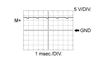
Throttle actuator positive terminal Item Content Symbols (Terminal No.) M+ (E12-5) - ME01 (E11-3) Tool Setting 5 V/DIV., 1 msec./DIV. Condition Idle after engine warm-up Tech Tips
The duty ratio varies depending on the throttle opening operation.
-
Waveform 2 (Reference)
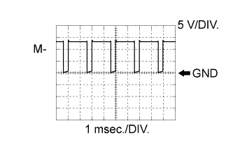
Throttle actuator negative terminal Item Content Symbols (Terminal No.) M- (E12-4) - ME01 (E11-3) Tool Setting 5 V/DIV., 1 msec./DIV. Condition Idle after engine warm-up Tech Tips
The duty ratio varies depending on the throttle opening operation.
-
Waveform 3 (Reference)
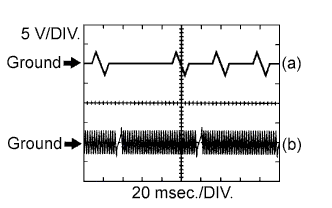
(a) Camshaft position sensor Item Content Symbols (Terminal No.) (a) G2+ (E12-26) - NE- (E12-34) Tool Setting 5 V/DIV., 20 msec./DIV. Condition Idle after engine warm-up (b) Crankshaft position sensor Item Content Symbols (Terminal No.) (b) NE+ (E12-27) - NE- (E12-34) Tool Setting 5 V/DIV., 20 msec./DIV. Condition Idle after engine warm-up Tech Tips
The wavelength becomes shorter as engine speed increases.
-
Waveform 4 (Reference)
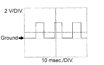
Vehicle speed signal Item Content Symbols (Terminal No.) SPD (E10-8) - E1 (E12-3) Tool Setting 2 V/DIV., 10 msec./DIV. Condition Driving at 40 km/h (25 mph) Tech Tips
The wavelength becomes shorter as vehicle speed increases.
-
Waveform 5 (Reference)
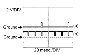
(a) Igniter IGT signal (from ECM to igniter) Item Content Symbols (Terminal No.) (a) IGT1 (E12-17) to IGT4 (E12-14) - E1 (E12-3) Tool Setting 2 V/DIV., 20 msec./DIV. Condition Idling (b) Igniter IGF signal (from igniter to ECM) Item Content Symbols (Terminal No.) (b) IGF1 (E12-23) - E1 (E12-3) Tool Setting 2 V/DIV., 20 msec./DIV. Condition Idling Tech Tips
The wavelength becomes shorter as engine speed increases.
-
Waveform 6 (Reference)
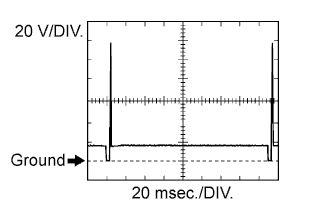
Fuel injector Item Content Symbols (Terminal No.) #10 (E11-6) to #40 (E11-1) - E01 (E12-7) Tool Setting 20 V/DIV., 20 msec./DIV. Condition Idling Tech Tips
The wavelength becomes shorter as engine speed increases.
-
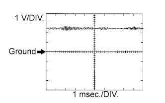
Waveform 7 (Reference)
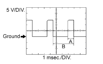
VVT OCV Item Content Symbols (Terminal No.) OC1+ (E12-13) - OC1- (E12-12) Tool Setting 5 V/DIV., 1 msec./DIV. Condition Accelerate slowly after engine warm-up Tech Tips
VVT OCV DUTY (%) = A/B x 100
-
Waveform 8 (Reference)
Knock sensor Item Content Symbols (Terminal No.) KNK1 (E12-29) - EKNK (E12-30) Tool Setting 0.01 to 10 V/DIV., 0.01 to 10 msec./DIV. Condition After warming up engine, keep engine speed at 4,000 rpm Tech Tips
-
The wavelength becomes shorter as engine speed increases.
-
The waveform and amplitudes displayed differ slightly depending on the vehicle.
-
-
Waveform 9 (Reference)
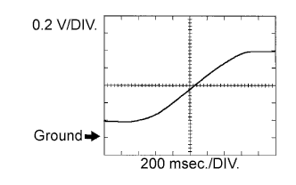
Heated oxygen (HO2) sensor (sensor 2) Item Content Symbols (Terminal No.) OX1B (E12-25) - E2 (E12-28) Tool Setting 0.2 V/DIV., 200 msec./DIV. Condition Engine maintained at 2,500 rpm when engine warmed up Tech Tips
In the Data List, item O2S B1 S2 shows the ECM input values from the rear HO2 sensor (sensor 2).
-
Waveform 10 (Reference)
Purge VSV Item Content Symbols (Terminal No.) PRG (E11-23) - E01 (E12-7) Tool Setting 10 V/DIV., 20 msec./DIV. Condition Idling Tech Tips
If the waveform is not similar to the illustration, check the waveform again after idling for 10 minutes or more.
-
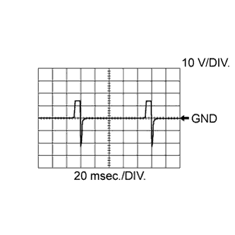
Waveform 11 (Reference)
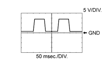
Terminal DI of air injection control driver Item Content Symbols (Terminal No.) AIDI (E11-20) - E1 (E12-3) Tool Setting 5 V/DIV., 50 msec./DIV. Condition Air injection system operates Tech Tips
The wavelength changes when the air injection control driver detects malfunction in the air injection system Click here
-
Waveform 12 (Reference)
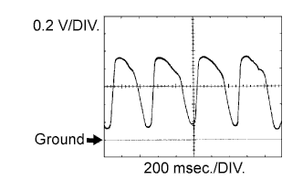
Heated oxygen (HO2) sensor (sensor 1) Item Content Symbols (Terminal No.) OX1A (E12-21) - E2 (E12-28) Tool Setting 0.2 V/DIV., 200 msec./DIV. Condition Engine maintained at 2,500 rpm when engine warmed up Tech Tips
In the Data List, item O2S B1 S1 shows the ECM input values from the rear HO2 sensor (sensor 1).