POWER SEAT SWITCH INSPECTION
PROCEDURE
INSPECT FRONT POWER SEAT SWITCH
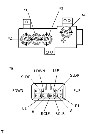
*1
Slide Switch
*2
Front Vertical Switch
*3
Lifter Switch
*4
Reclining Switch
*a
Component without harness connected
(Front Power Seat Switch)
Check the resistance of the slide switch.
Measure the resistance according to the value(s) in the table below.
Standard Resistance
Tester Connection
Switch Condition
Specified Condition
5 (SLDF) - 8 (B)
5 (SLDF) - 7 (B1)
Front position
Below 1 Ω
2 (SLDR) - 11 (E)
2 (SLDR) - 12 (E1)
5 (SLDF) - 11 (E)
5 (SLDF) - 12 (E1)
Neutral
Below 1 Ω
2 (SLDR) - 11 (E)
2 (SLDR) - 12 (E1)
5 (SLDF) - 11 (E)
5 (SLDF) - 12 (E1)
Rear position
Below 1 Ω
2 (SLDR) - 8 (B)
2 (SLDR) - 7 (B1)
If the result is not as specified, replace the front power seat switch.
Check the resistance of the front vertical switch.
Measure the resistance according to the value(s) in the table below.
Standard Resistance
Tester Connection
Switch Condition
Specified Condition
1 (FUP) - 8 (B)
1 (FUP) - 7 (B1)
Up position
Below 1 Ω
6 (FDWN) - 11 (E)
6 (FDWN) - 12 (E1)
1 (FUP) - 11 (E)
1 (FUP) - 12 (E1)
Neutral
Below 1 Ω
6 (FDWN) - 11 (E)
6 (FDWN) - 12 (E1)
1 (FUP) - 11 (E)
1 (FUP) - 12 (E1)
Down position
Below 1 Ω
6 (FDWN) - 8 (B)
6 (FDWN) - 7 (B1)
If the result is not as specified, replace the front power seat switch.
Check the resistance of the lifter switch.
Measure the resistance according to the value(s) in the table below.
Standard Resistance
Tester Connection
Switch Condition
Specified Condition
3 (LUP) - 8 (B)
3 (LUP) - 7 (B1)
Up position
Below 1 Ω
4 (LDWN) - 11 (E)
4 (LDWN) - 12 (E1)
3 (LUP) - 11 (E)
3 (LUP) - 12 (E1)
Neutral
Below 1 Ω
4 (LDWN) - 11 (E)
4 (LDWN) - 12 (E1)
3 (LUP) - 11 (E)
3 (LUP) - 12 (E1)
Down position
Below 1 Ω
4 (LDWN) - 8 (B)
4 (LDWN) - 7 (B1)
If the result is not as specified, replace the front power seat switch.
Check the resistance of the reclining switch.
Measure the resistance according to the value(s) in the table below.
Standard Resistance
Tester Connection
Switch Condition
Specified Condition
10 (RCLF) - 8 (B)
10 (RCLF) - 7 (B1)
10 (RCLF) - 1 (FUP)
10 (RCLF) - 6 (FDWN)
Front position
Below 1 Ω
9 (RCLR) - 11 (E)
9 (RCLR) - 12 (E1)
10 (RCLF) - 11 (E)
10 (RCLF) - 12 (E1)
Neutral
Below 1 Ω
9 (RCLR) - 11 (E)
9 (RCLR) - 12 (E1)
10 (RCLF) - 11 (E)
10 (RCLF) - 12 (E1)
Rear position
Below 1 Ω
9 (RCLR) - 8 (B)
9 (RCLR) - 7 (B1)
9 (RCLR) - 1 (FUP)
9 (RCLR) - 6 (FDWN)
If the result is not as specified, replace the front power seat switch.