ECD SYSTEM (w/o EGR Cooler), Diagnostic DTC:P0488
| DTC Code | DTC Name |
|---|---|
| P0488 | Exhaust Gas Recirculation Throttle Position Control Range / Performance |
DESCRIPTION
The ECM opens and closes the throttle valve using the rotary solenoid type actuator. The exhaust gas recirculation volume is controlled by opening and closing the valve. Also, engine vibration and noise is reduced by closing the valve when the engine is stopped.
| DTC No. | DTC Detection Condition | Trouble Area |
|---|---|---|
| P0488 | When either condition below is met:
|
|
Tech Tips
After confirming DTC P0488, check the throttle position.
| Reference | ||||
|---|---|---|---|---|
|
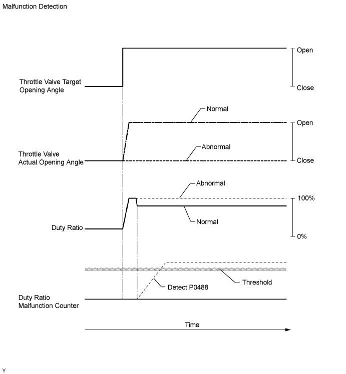
MONITOR DESCRIPTION
The ECM opens and closes the throttle valve by adjusting the duration of current flowing to the rotary solenoid (duty ratio). If the throttle valve does not move smoothly or is stuck, the duty ratio during the valve movement control increases or decreases greatly, the ECM will determine that the throttle valve has a malfunction and illuminate the MIL.
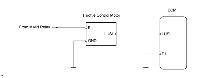
WIRING DIAGRAM
INSPECTION PROCEDURE
Tech Tips
-
Read freeze frame data using the intelligent tester. Freeze frame data records the engine conditions when a malfunction is detected. When troubleshooting, freeze frame data can help determine if the vehicle was running or stopped, if the engine was warmed up or not, and other data from the time the malfunction occurred.
-
After warming up the engine, DTC P0488 is set 1 second or more after quickly accelerating the engine from idling.
Note
If the ECM is replaced, the new ECM needs initialization Click here.
PROCEDURE
-
CHECK OTHER DTC OUTPUT (IN ADDITION TO DTC P0448)
-
Connect the intelligent tester to the DLC3.
-
Turn the ignition switch ON and turn the intelligent tester ON.
-
Enter the following menus: Powertrain / Engine / DTC.
-
Read the DTCs Click here.
Result Display (DTC Output) Proceed to P0488 A P0488 and P0122 and/or P0123 B Tech Tips
If any other codes besides P0488 are output, perform troubleshooting for those DTCs first.
B 
GO TO RELEVANT DTC CHART
A 
-
-
CHECK IF DTC OUTPUT RECURS (DTC P0448 OUTPUT)
-
Connect the intelligent tester to the DLC3.
-
Turn the ignition switch ON and turn the intelligent tester ON.
-
Enter the following menus: Powertrain / Engine / DTC / Clear.
-
Clear the DTCs Click here.
-
Start the engine and perform a quick engine acceleration from idling to 3,000 rpm 3 times.
-
Enter the following menus: Powertrain / Engine / DTC.
-
Read the DTCs Click here.
Result Display (DTC output) Proceed to P0488 A No output B Tech Tips
The normal operation of the throttle valve is as follows.
Reference Condition Throttle Position Moment when accelerator pedal is further depressed or released at 3,000 rpm Opening angle varies smoothly
B
CHECK FOR INTERMITTENT PROBLEMS
A
-
-
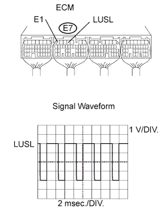
CHECK ECM (LUSL SIGNAL)
-
While revving the engine, check the waveform of the ECM connector using an oscilloscope.
Standard voltage Tester Connection Specified Condition E7-4 (LUSL) - E7-7 (E1) Correct waveform is shown Tool Setting Condition 1 V/DIV., 2 msec./DIV. Racing engine with warm engine Tech Tips
The waveform varies depending on the diesel throttle signal operation.
NG
REPLACE ECM
OK
-
-
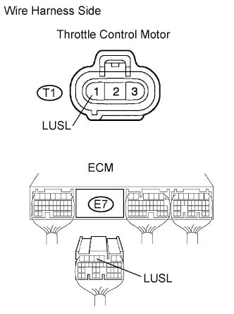
CHECK WIRE HARNESS (THROTTLE CONTROL MOTOR - ECM)
-
Disconnect the T1 motor connector.
-
Disconnect the E7 ECM connector.
-
Measure the resistance of the wire harness side connectors.
Standard resistance Tester Connection Specified Condition T1-1 (DUTY) - E7-4 (LUSL) Below 1 Ω T1-1 (DUTY) or E7-4 (LUSL) - Body ground 10 kΩ or higher
NG
REPAIR OR REPLACE HARNESS AND CONNECTOR
OK 
REPLACE DIESEL THROTTLE BODY ASSEMBLY
-