SHIFT AND SELECT ACTUATOR REMOVAL
PROCEDURE
PRECAUTION
Note:Make sure that the gear is in the neutral position before removing the shift and select actuator assembly. If the gear cannot be shifted to the neutral position due to malfunctions in the actuator and/or transaxle gear, remove the plug from the shift and select actuator assembly and confirm the slit is in the neutral position. If not, perform the following operation.
-
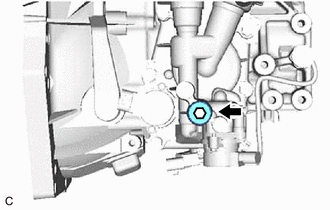
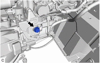
Remove the plug from the shift and select actuator assembly.
Look through the plug and check that the slit of the shift and select actuator assembly is in the position shown in the illustration.
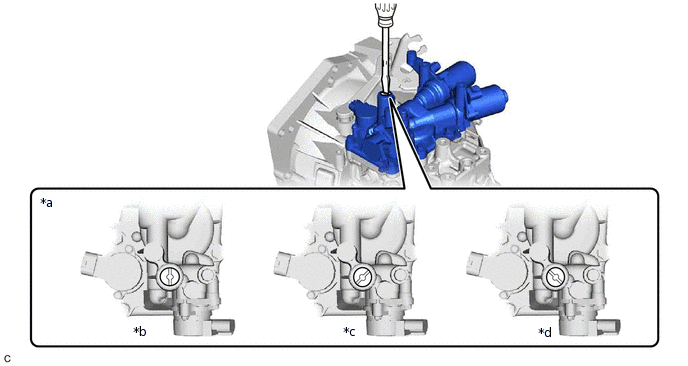
*a
Shift Slit Position
*b
N
*c
2nd, 4th or R
*d
1st, 3rd or 5th
If not, turn it with a screwdriver.
Note:Make sure that the slit is in position *b and not in position *c or *d shown in the illustration when removing the shift and select actuator assembly, otherwise the shift and select actuator assembly, No. 1 gear shift head, No. 2 gear shift fork shaft or No. 3 gear shift head may be deformed.
Clean and degrease the plug and installation hole in the shift and select actuator assembly.
-
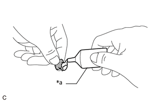
*a
Adhesive
Apply adhesive to the plug threads.
Adhesive
Toyota Genuine Adhesive 1344, Three Bond 1344 or equivalent
Note:In order to ensure proper installation of the plug, apply adhesive to the plug and install it within 10 minutes of adhesive application.
-
Install the plug to the shift and select actuator assembly.
40.2 N*m
410 kgf*cm
30 ft.*lbf
-
REMOVE CLUTCH ACTUATOR ASSEMBLY
DISCONNECT WIRE HARNESS
-
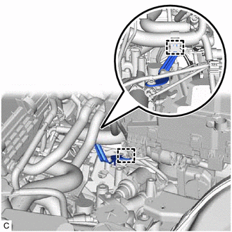
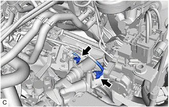
Disengage the 2 wire harness clamps.
-
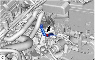
Remove the bolt and wire harness clamp bracket from the shift and select actuator assembly.
-
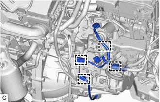
Disconnect the 2 shift and select actuator assembly connectors.
-

*a
Select Stroke Sensor Connector
*b
Park/Neutral Position Switch Assembly Connector
*c
Shift Stroke Sensor Connector
*d
Back-up Light Switch Assembly Connector
*e
Transmission Revolution Sensor Connector
Disconnect the select stroke sensor connector.
Disconnect the park/neutral position switch assembly connector.
Disconnect the shift stroke sensor connector.
Disconnect the back-up light switch assembly connector.
Disconnect the transmission revolution sensor connector.
-
Disengage the 4 wire harness clamps.
-
REMOVE PARK/NEUTRAL POSITION SWITCH ASSEMBLY

Disconnect the park/neutral position switch assembly connector.
-
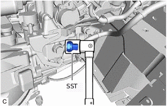
Using SST, remove the park/neutral position switch assembly and gasket from the multi-mode manual transaxle assembly.
09817-16011
REMOVE NO. 1 LOCK BALL ASSEMBLY
-
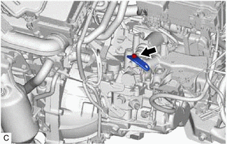
Using a 18 mm socket wrench, remove the No. 1 lock ball assembly from the manual transmission case.
-
REMOVE SHIFT AND SELECT ACTUATOR ASSEMBLY
-
Remove the bolt and wire harness clamp bracket from the shift and select actuator assembly.
-
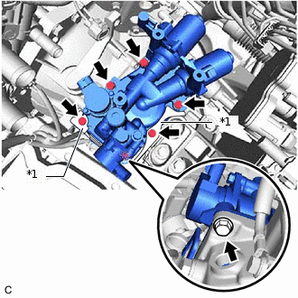
*1
Wire Harness Clamp Bracket
Remove the 6 bolts, 2 wire harness clamp brackets and shift and select actuator assembly from the manual transmission case.
-