TURBOCHARGER (for DPF) REMOVAL
-
DISCONNECT CABLE FROM NEGATIVE BATTERY TERMINAL
Note
When disconnecting the cable, some systems need to be initialized after the cable is reconnected Click here.
-
REMOVE FRONT EXHAUST PIPE ASSEMBLY
-
REMOVE INTERCOOLER ASSEMBLY
-
REMOVE NO. 1 ENGINE UNDER COVER
-
REMOVE NO. 2 ENGINE UNDER COVER
-
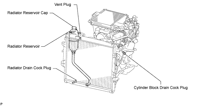
DRAIN ENGINE COOLANT
CAUTION:
Do not remove the radiator reservoir cap while the engine and radiator are still hot. Pressurized, hot engine coolant and steam may be released and cause serious burns.
-
Loosen the radiator drain cock plug.
Tech Tips
Collect the coolant in a container and dispose of it according to the regulations in your area.
-

Drain the coolant by removing the reservoir cap and, using a wrench, remove the vent plug.
-
Loosen the cylinder block drain cock plug.
-
-
REMOVE FRONT FENDER APRON SEAL UPPER
-
Remove the 5 clips and front fender apron seal upper.
-
-
REMOVE FRONT FENDER SEAL
-
Remove the 5 clips and front fender seal.
-
-
REMOVE AIR CLEANER ASSEMBLY
-
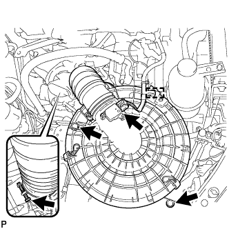
Detach the wire harness clamp and disconnect the mass air flow meter connector.
-
Loosen the hose clamp and disconnect No. 1 air cleaner hose from the compressor inlet elbow.
-
Remove the 2 bolts and air cleaner assembly together with the No. 1 air cleaner hose.
-
-
REMOVE VENTILATION PIPE
-
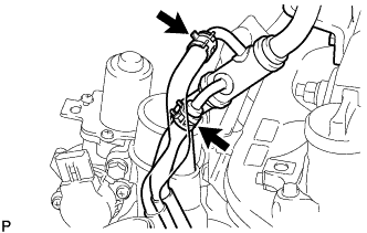
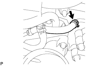
for Cold Area Specification Vehicles:
Disconnect the No.12 water by-pass hose and No. 13 water by-pass hose.
-
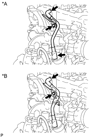
Text in Illustration *A except Cold Area Specification Vehicles *B for Cold Area Specification Vehicles Remove the bolt and ventilation pipe.
-
-
REMOVE COMPRESSOR INLET ELBOW
-
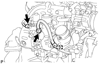
Disconnect the 2 connectors and detach the wire harness clamp.
-
Disconnect the No. 1 turbo water hose.
-
Disconnect the No. 2 water by-pass hose.
Text in Illustration *A except Cold Area Specification Vehicles *B for Cold Area Specification Vehicles *1 No. 2 Water By-pass Hose *2 No. 9 Water By-pass Hose *3 No. 13 Water By-pass Hose - - -
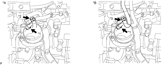
except Cold Area Specification Vehicles:
Disconnect the No. 9 water by-pass hose.
-
for Cold Area Specification Vehicles:
Remove the No. 13 water by-pass hose.
-
Remove the 2 nuts, compressor inlet elbow and gasket.
-
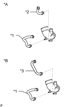
Text in Illustration *A except Cold Area Specification Vehicles *B for Cold Area Specification Vehicles *1 No. 7 Water By-pass Hose *2 No. 9 Water By-pass Hose *3 No. 12 Water By-pass Hose Remove the No. 7 water by-pass hose.
-
except Cold Area Specification Vehicles:
Remove the No. 9 water by-pass hose.
-
for Cold Area Specification Vehicles:
Remove the No. 12 water by-pass hose.
-
-
REMOVE NO. 1 TURBO INSULATOR
-
Remove the 2 bolts and No. 1 turbo insulator.
-
-
REMOVE NO. 1 EXHAUST MANIFOLD HEAT INSULATOR
-
Remove the bolt and No. 1 exhaust manifold heat insulator.
-
-
REMOVE NO. 2 EXHAUST MANIFOLD HEAT INSULATOR
-
Remove the 2 bolts and No. 2 exhaust manifold heat insulator.
-
-
REMOVE NO. 3 EXHAUST MANIFOLD HEAT INSULATOR
-
Remove the 2 bolts and No. 3 exhaust manifold heat insulator.
-
-
REMOVE TURBINE OUTLET ELBOW STAY
-
Detach the wire harness clamp and remove the bolt, nut and turbine outlet elbow stay.
-
-
REMOVE NO. 2 TURBINE OUTLET ELBOW
-
Remove the 3 nuts, No. 2 turbine outlet elbow and gasket.
-
-
DISCONNECT NO. 1 FUEL PIPE
-
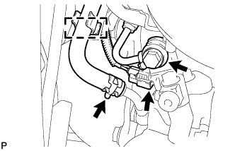
Detach the hose clamp and disconnect the No. 4 turbo water hose from the No. 4 water by-pass pipe.
-
Disconnect the exhaust fuel addition injector connector.
-
Remove the union bolt and gasket from the No. 1 fuel pipe.
-
Disconnect the No. 1 fuel pipe from the turbine outlet elbow.
-
-
REMOVE TURBINE OUTLET ELBOW
-
Disconnect the No. 3 turbo water hose from the No. 3 water by-pass pipe.
-
Remove the 3 nuts, turbine outlet elbow and gasket.
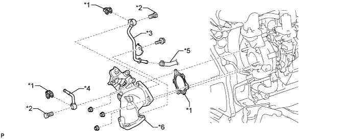
Text in Illustration *1 Gasket *2 Union Bolt *3 No. 3 Water By-pass Pipe *4 No. 4 Water By-pass Pipe *5 No. 3 Turbo Water Hose *6 Turbine Outlet Elbow -
Remove the bolt, union bolt, gasket and No. 3 water by-pass pipe from the turbine outlet elbow.
-
Remove the union bolt, gasket and No. 4 water by-pass pipe from the turbine outlet elbow.
-
-
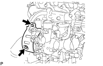
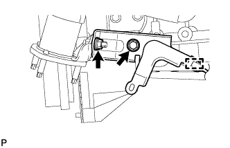
REMOVE TURBOCHARGER STAY
-
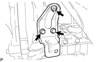
Remove the 2 bolts, nut and turbocharger stay.
-
-
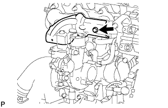
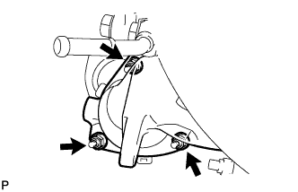
REMOVE TURBO OIL INLET PIPE SUB-ASSEMBLY
-
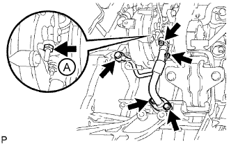
Remove the 2 bolts, 2 nuts, union bolt, turbo oil inlet pipe sub-assembly and 3 gaskets.
Note
Do not loosen the nut labeled A in the illustration.
-
-
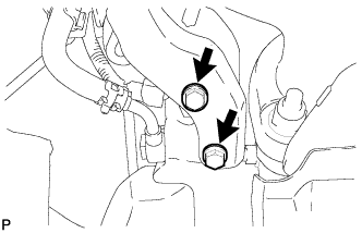
REMOVE TURBOCHARGER SUB-ASSEMBLY
-
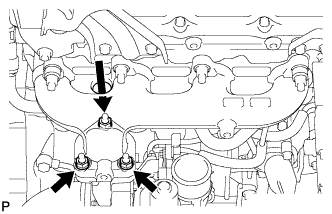
Remove the 3 nuts, turbocharger sub-assembly and gasket.
-
-
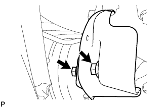
REMOVE NO. 1 TURBO WATER PIPE SUB-ASSEMBLY
-
Remove the No. 1 turbo water hose and No. 3 turbo water hose.
-
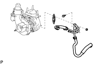
Remove the 2 nuts, bolt, No. 1 turbo water pipe sub-assembly and gasket.
-