REAR AXLE HUB REMOVAL

CAUTION / NOTICE / HINT
The necessary procedures (adjustment, calibration, initialization, or registration) that must be performed after parts are removed, installed, or replaced during the rear axle hub removal/installation are shown below.
| Necessary Procedure After Parts Removed/Installed/Replaced | ||||||||||||||||||||||
|---|---|---|---|---|---|---|---|---|---|---|---|---|---|---|---|---|---|---|---|---|---|---|
|
Note
-
When the brake pedal is first depressed after replacing the brake pads or pushing back the disc brake piston, DTC C1341, C1342, C1343 and/or C1344 may be stored. As there is no malfunction, clear the DTCs.
-
While the battery is connected, even if the engine switch is off, the brake control system activates when the brake pedal is depressed or any door courtesy switch is turned on. Therefore, when servicing, do not depress the brake pedal or open/close the doors while the battery is connected. (w/o Vacuum Brake Booster)
-
Be sure to read the "PRECAUTION" thoroughly before servicing.
Tech Tips
-
Use the same procedure for the RH and LH side.
-
The following procedure is for the LH side.
PROCEDURE
-
AIR SUSPENSION CONTROL PROHIBITED (w/ Air Suspension)
-
REMOVE REAR WHEEL
-
DISCONNECT REAR HEIGHT CONTROL SENSOR SUB-ASSEMBLY LH
-
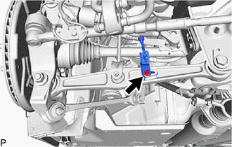
Disconnect the bolt and rear height control sensor sub-assembly LH.
-
-
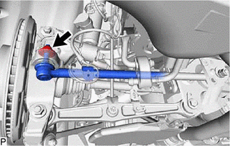
DISCONNECT REAR STABILIZER LINK ASSEMBLY LH
-
REMOVE REAR AXLE SHAFT NUT LH
-
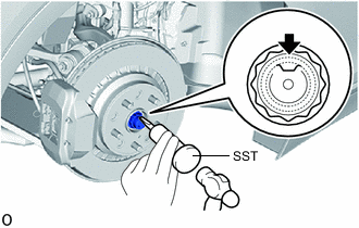
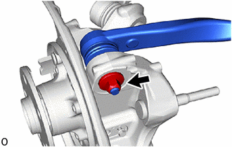
Using SST and a hammer, release the staked part of the rear axle shaft nut LH.
- SST
- 09930-00010
Note
-
Set SST in the groove with its flat surface facing upward.
-
Do not grind the tip of SST with a grinder or other tools.
-
Fully unstake the rear axle shaft nut LH.
-
Do not damage the threads of the rear drive shaft assembly LH.
-
Using a 32 mm socket wrench, remove the rear axle shaft nut LH.
-
-
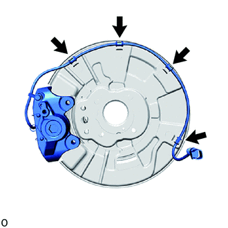
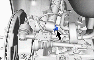
DISCONNECT SKID CONTROL SENSOR WIRE
-
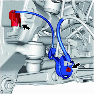
for LH Side:
-
Disconnect the speed sensor connector from the speed sensor LH.
Note
-
Be careful not to damage the speed sensor.
-
Prevent foreign matter from adhering to the speed sensor.
-
-
Remove the bolt and sensor clamp.
-
-
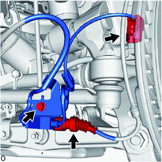
for RH Side:
-
Disconnect the speed sensor connector from the speed sensor RH.
Note
-
Be careful not to damage the speed sensor.
-
Prevent foreign matter from adhering to the speed sensor.
-
-
Disconnect the pad wear indicator connector.
-
Remove the bolt and sensor clamp.
-
-
-
REMOVE REAR SPEED SENSOR LH
-
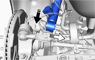
DISCONNECT REAR DISC BRAKE CYLINDER ASSEMBLY
-
for RH side:
-
Detach the 2 clamps to disconnect the pad wear indicator assembly.
-
-
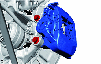
Remove the 2 bolts and disconnect disc brake cylinder assembly LH from the steering knuckle.
Note
Use wire or an equivalent tool to keep the rear disc brake cylinder assembly LH from hanging down by the flexible hose.
-
-
REMOVE PARKING BRAKE SHOE ADJUSTING HOLE PLUG
-
for 4-Pot Caliper:
-
except 4-Pot Caliper:
-
-
REMOVE REAR DISC LH
-
for 4-Pot Caliper:
-
except 4-Pot Caliper:
-
-
REMOVE PARKING BRAKE
-
DISCONNECT REAR SHOCK ABSORBER ASSEMBLY LH (w/o Air Suspension)
-
Remove the nut from the rear shock absorber with coil spring (lower side).
-

Remove in this Direction (1) 
Remove in this Direction (2) Remove the rear shock absorber with coil spring and washer as shown in the illustration.
-
-
DISCONNECT REAR PNEUMATIC CYLINDER WITH SHOCK ABSORBER ASSEMBLY LH (w/ Air Suspension)
Tech Tips
Use the same procedure for the rear shock absorber assembly LH.
-
DISCONNECT REAR NO. 2 SUSPENSION ARM ASSEMBLY LH
-
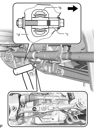
*a A *b Arm *c Slide Pin *d Axle Carrier 
Front of the Vehicle Using a plastic-faced hammer or equivalent, strike the part labeled A from the rear of the vehicle to maintain the clearance at the slide pin area.
Note
Be careful not to damage the arm.
-
Remove the nut, bolt and washer.
-
-
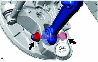
DISCONNECT LOWER CONTROL ARM ASSEMBLY LH
-
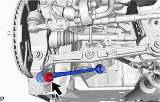
Remove the nut.
-
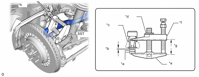
Install 2 SST (spacer B) onto the lower control arm assembly LH so that there is a space of approximately 1 mm (0.0394 in.) between the arm and spacers.
- SST
- 09960-20010 ( 09961-02060 )
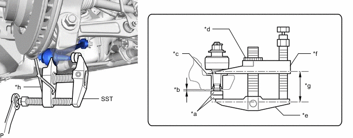
*a SST (Spacer B) *b 1 mm (0.0394 in.) *c Spacer *d Center Nut *e Body *f Claw *g Parallel *h String Note
-
Make sure to install the spacers (SST spacer B) as the rear axle carrier sub-assembly LH spacer may shift.
-
As SST may become damaged, make sure the space between the arm and spacers is not 1 mm (0.0394 in.) or less.
-
Using SST, disconnect the lower control arm assembly LH from the rear axle carrier sub-assembly LH.
- SST
- 09960-20010 ( 09961-02010 )
Note
-
Apply molybdenum grease to the bolt threads and end of SST bolt.
-
Do not damage the dust cover.
-
As the dust cover may be damaged, adjust SST with the center nut so that the body and claw are parallel.
-
Make sure to tie the string of SST to the vehicle to prevent SST from dropping.
-
-
DISCONNECT TOE CONTROL LINK SUB-ASSEMBLY LH (w/o Dynamic Rear Steering)
-
Remove the nut.
-
Install 2 SST (spacer B) onto the toe control link sub-assembly LH so that there is a space of approximately 1 mm (0.0394 in.) between the arm and spacers.
- SST
- 09960-20010 ( 09961-02060 )
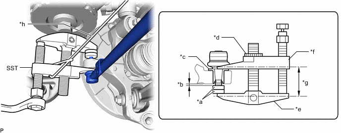
*a SST (Spacer B) *b 1 mm (0.0394 in.) *c Spacer *d Center Nut *e Body *f Claw *g Parallel *h String Note
-
Make sure to install the spacers (SST spacer B) as the rear axle carrier sub-assembly LH spacer may shift.
-
As SST may become damaged, make sure the space between the arm and spacers is not 1 mm (0.0394 in.) or less.
-
Using SST, disconnect the toe control link sub-assembly LH from the rear axle carrier sub-assembly LH.
- SST
- 09960-20010 ( 09961-02010 )
Note
-
Apply molybdenum grease to the bolt threads and end of SST bolt.
-
Do not damage the dust cover.
-
As the dust cover may be damaged, adjust SST with the center nut so that the body and claw are parallel.
-
Make sure to tie the string of SST to the vehicle to prevent SST from dropping.
-
-
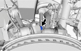
DISCONNECT REAR STEERING TIE ROD ASSEMBLY LH (w/ Dynamic Rear Steering)
-
DISCONNECT REAR NO. 1 SUSPENSION ARM ASSEMBLY LH
-
Remove the nut.
-
Install 2 SST (spacer A) onto the rear No. 1 suspension arm assembly LH so that there is a space of approximately 1 mm (0.0394 in.) between the arm and spacers.
- SST
- 09960-20010 ( 09961-02050 )
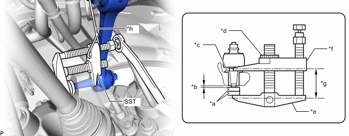
*a SST (Spacer A) *b 1 mm (0.0394 in.) *c Spacer *d Center Nut *e Body *f Claw *g Parallel *h String Note
-
Make sure to install the spacers (SST spacer A) as the rear axle carrier sub-assembly LH spacer may shift.
-
As SST may become damaged, make sure the space between the arm and spacers is not 1 mm (0.0394 in.) or less.
-
Using SST, disconnect the rear No. 1 suspension arm assembly LH from the rear axle carrier sub-assembly LH.
- SST
- 09960-20010 ( 09961-02010 )
Note
-
Apply molybdenum grease to the bolt threads and end of SST bolt.
-
Do not damage the dust cover.
-
As the dust cover may be damaged, adjust SST with the center nut so that the body and claw are parallel.
-
Make sure to tie the string of SST to the vehicle to prevent SST from dropping.
-
-
DISCONNECT REAR UPPER CONTROL ARM ASSEMBLY LH
-
Remove the nut.
-
Install 2 SST (spacer A) onto the rear upper control arm assembly LH so that there is a space of approximately 1 mm (0.0394 in.) between the arm and spacers.
- SST
- 09960-20010 ( 09961-02050 )
*a SST (Spacer A) *b 1 mm (0.0394 in.) *c Spacer *d Center Nut *e Body *f Claw *g Parallel *h String Note
-
Make sure to install the spacers (SST spacer A) as the rear axle carrier sub-assembly LH spacer may shift.
-
As SST may become damaged, make sure the space between the arm and spacers is not 1 mm (0.0394 in.) or less.
-
Using SST, disconnect the rear upper control arm assembly LH from the rear axle carrier sub-assembly LH.
- SST
- 09960-20010 ( 09961-02010 )
Note
-
Apply molybdenum grease to the bolt threads and end of SST bolt.
-
Do not damage the dust cover.
-
As the dust cover may be damaged, adjust SST with the center nut so that the body and claw are parallel.
-
Make sure to tie the string of SST to the vehicle to prevent SST from dropping.
-
-
REMOVE REAR AXLE ASSEMBLY
-
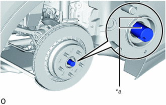
*a Matchmark Place matchmarks on the rear axle hub and bearing assembly LH and rear drive shaft assembly LH as shown in the illustration.
-
Using a plastic-faced hammer, lightly tap the end of the drive shaft assembly and disengage the drive shaft and rear axle carrier.
Tech Tips
If the connection is stiff, tap the end of the drive shaft using a brass bar and hammer.
-
Pull the rear axle assembly LH toward the vehicle exterior while supporting the rear drive shaft assembly.
Note
-
Do not damage the drive shaft outboard joint boot.
-
Suspend the drive shaft assembly with rope, wire or an equivalent tool.
-
-
-
REMOVE REAR NO. 1 WHEEL BEARING DUST DEFLECTOR LH
-
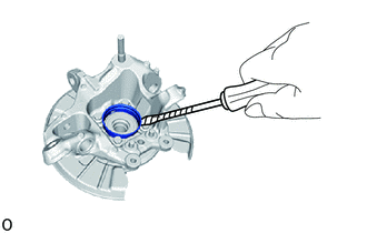
Using a screwdriver, remove the rear No. 1 wheel bearing dust deflector LH from the rear axle carrier.
Note
The rear axle carrier is made from aluminum. Therefore, take care that it does not become dented.
-
-
REMOVE REAR AXLE HUB AND BEARING ASSEMBLY LH
-
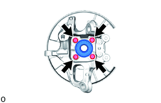
Remove the 4 bolts and rear axle hub and bearing assembly LH from the rear axle carrier.
-
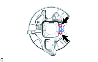
Remove the 2 nuts and parking brake anchor block sub-assembly, cable support bracket and parking brake plate from the rear axle carrier.
-