HEATED WINDSHIELD DEFROSTER SYSTEM TERMINALS OF ECU
-
CHECK AIR CONDITIONING AMPLIFIER ASSEMBLY
-
Disconnect the K54 air conditioning amplifier assembly connector.
-
Measure the voltage and resistance according to the value(s) in the table below.
Tech Tips
Measure the values on the wire harness side with the connector disconnected.
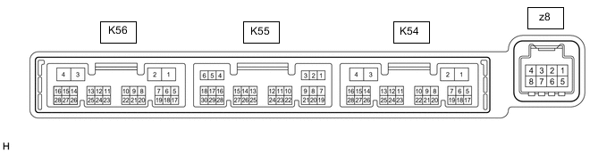
Terminal No. (Symbol) Wiring Color Terminal Description Condition Specified Condition K54-2 (IG+) - K54-4 (GND) LA-GR - W-B Power source (IG) Engine switch on (IG) 11 to 14 V Engine switch off Below 1 V K54-1 (B) - K54-4 (GND) LA-B - W-B Battery power supply Always 11 to 14 V K54-4 (GND) - Body ground W-B - Body ground Ground Always Below 1 Ω -
Reconnect the K54 air conditioning amplifier assembly connector.
-
Measure the voltage according to the value(s) in the table below.
Terminal No. (Symbol) Wiring Color Terminal Description Condition Specified Condition K54-17 (FDEF) - K54-4 (GND) GR - W-B Window deicer signal Engine switch on (IG), Front window deicer switch off 11 to 14 V Engine switch on (IG), Front window deicer switch on Below 2.2 V K55-29 (DFAC) - K54-4 (GND) G - W-B Window deicer signal Engine switch on (IG), Front window deicer switch off Below 1 V Engine switch on (IG), Front window deicer switch on 11 to 14 V K55-2 (SG-2) - Body ground W - Body ground Ground for thermistor assembly Always Below 1 V K55-13 (TAM) - K55-2 (SG-2) R - W Thermistor assembly signal Engine switch on (IG), Ambient temperature: 25°C (77°F) 1.05 to 1.45 V Engine switch on (IG), Ambient temperature: 40°C (104°F) 0.64 to 0.87 V
-