STEERING COLUMN ASSEMBLY(for Manual Tilt and Manual Telescopic Steering Column) REMOVAL
CAUTION / NOTICE / HINT
Note
-
Do not replace the spiral with sensor cable sub-assembly with the battery connected and the engine switch on (IG).
-
Do not rotate the spiral with sensor cable sub-assembly when the following conditions are met: 1) The steering wheel is removed, 2) the battery is connected,and 3) the engine switch is on (IG).
-
Ensure that the steering wheel is installed and aligned straight when inspecting the steering sensor.
Tech Tips
-
Use the same procedure for RHD and LHD vehicles.
-
The procedure listed below is for LHD vehicles.
PROCEDURE
-
PLACE FRONT WHEELS FACING STRAIGHT AHEAD
-
REMOVE STEERING WHEEL ASSEMBLY
-
REMOVE LOWER STEERING COLUMN COVER
Note
Failure to follow the correct removal procedure may damage the claws.
-
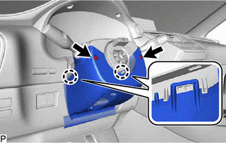
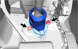
Remove the 2 screws.
-
Release the tilt lever.
-
Press both sides of the lower steering column cover to detach the 2 claws.
-

Remove in this Direction (1) 
Remove in this Direction (2) Pull the steering column lower cover toward the rear of the vehicle and detach the lower side claw to remove the steering column lower cover.
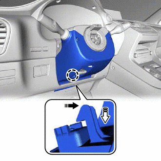
Note
-
If the steering column is pushed downward with heavy force before the claw is detached, the resin stay attachment may become damaged.
-
Do not damage the tilt and telescopic switch.
-
-
-
REMOVE UPPER STEERING COLUMN COVER
-
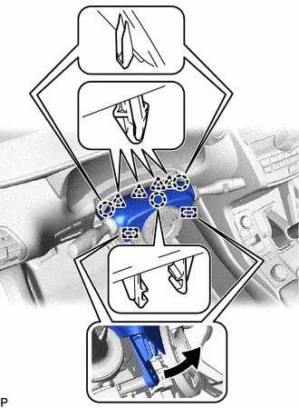
Detach the 3 claws, 4 clips and 2 pins and remove the upper steering column cover.
-
-
REMOVE COMBINATION SWITCH ASSEMBLY WITH SPIRAL CABLE SUB-ASSEMBLY
-
Disconnect the connectors from the combination switch assembly with spiral cable sub-assembly.
-
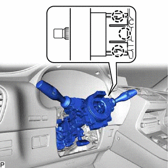
Detach the 3 claws. Remove the combination switch assembly with spiral cable sub-assembly from the electric power steering column sub-assembly.
-
-
REMOVE UPPER INSTRUMENT PANEL SUB-ASSEMBLY
-
REMOVE LOWER NO. 1 INSTRUMENT PANEL AIRBAG ASSEMBLY
-
REMOVE COLUMN HOLE COVER SILENCER SHEET
-
Fold back the floor carpet, and then remove the 2 clips and column hole cover silencer sheet.
-
-
DISCONNECT NO. 2 STEERING INTERMEDIATE SHAFT ASSEMBLY
-
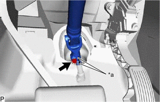
*a Matchmark Place matchmarks on the steering intermediate shaft and No. 2 steering intermediate shaft assembly.
-
Remove the bolt.
-
Disconnect the No. 2 steering intermediate shaft assembly from the steering intermediate shaft assembly.
-
-
REMOVE NO. 1 AIR DUCT
-
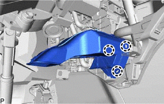
Detach the 3 claws and remove the No. 1 air duct.
Note
-
When removing, do not crack or deform the upper heater case of the air conditioning radiator assembly.
-
If the No. 1 air duct is reused, it may fall off or abnormal noise may occur. Therefore, make sure to replace with a new one.
-
-
-
REMOVE ELECTRIC POWER STEERING COLUMN SUB-ASSEMBLY
-
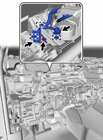
Disconnect the 2 connectors and detach the 3 clamps.
-
Remove the bolt and disconnect the harness cable.
-
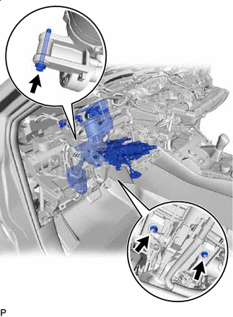
Remove the bolt, 2 nuts and electric power steering column sub-assembly.
Note
-
Do not release the tilt lever when the electric power steering column sub-assembly is not installed to the vehicle.
-
Do not drop or strike the electric power steering column sub-assembly. If dropped or struck, replace it with a new one.
-
-
-
REMOVE NO. 2 STEERING INTERMEDIATE SHAFT ASSEMBLY
-
Remove the bolt.
Note
Do not remove the No. 2 steering intermediate shaft assembly from the electric power steering column sub-assembly.
-
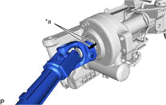
*a Matchmark Put matchmarks on the No. 2 steering intermediate shaft assembly and electric power steering column sub-assembly.
-
Remove the No. 2 steering intermediate shaft assembly from the electric power steering column sub-assembly.
-