NAVIGATION SYSTEM / MULTI INFORMATION SYSTEM
-
FUNCTION OF MAIN COMPONENTS
Component Function Radio and Display Receiver Assembly
-
Extension Box (Navigation ECU)
Receives and processes the data that is input from various components, displays various pieces of information and operating conditions on the screen, and provides voice guidance. Navigation Antenna Assembly*1 Receives signals from GPS satellites and transmits them to the extension box (navigation ECU). Combination Meter Assembly
-
Transmits vehicle speed signals to the stereo component amplifier assembly*2 or radio and display receiver assembly.
-
Displays information such as audio status information received from the audio head unit on the multi-information display.
-
Sends operation signals to the audio head unit when the audio system is operated via the multi-information display.
Steering Pad Switch Assembly Enables the user to operate the navigation system from the steering pad switches. Shift Lever Position Sensor Transmits the R position signal to the radio and display receiver assembly. No. 1 Stereo Jack Adapter Assembly
-
Sends audio and/or video signals to the audio head unit when an auxiliary device is connected.
-
Communicates with the audio head unit via a USB communication line when a USB memory device, portable audio player (USB type) or Apple product is connected.
Telephone Microphone Assembly Recognizes speech during voice recognition system operation and sends the audio signal to the radio and display receiver assembly. Amplifier Antenna Assembly
-
AM
-
FM
-
GPS Antenna*3
-
Receives radio broadcasting signals (AM/FM).
-
Amplifies the received radio broadcasting signals using the built-in amplifier antenna assembly, and sends them to the audio head unit.
-
Receives signals from GPS satellites and transmits them to the navigation receiver assembly.*3
Telematics Transceiver*4 Sends microphone voice signals sent from the telephone microphone assembly to the radio and display receiver assembly.
-
*1: Except models for Russia
-
*2: Models with 11-speaker system
-
*3: Models for Russia
-
*4: Models with ERA-GLONASS
-
-
FUNCTION
-
Navigation Screen
-
The navigation computer calculates the present position and direction of travel, determines a route and calculates the driving distance based on the following information sources:
-
Map data in the extension box (navigation ECU)
-
Global Positioning System (GPS) satellites
-
Built-in gyro sensor
-
Vehicle speed signal
-
Reverse signal
-
Parking brake signal
-
Radio Data System Traffic Message Channel (RDS-TMC) signal
Item Function Map Display Taillight-interlocked Map Color Change Changes the color of the map screen when the taillights are turned on. North Up/Heading Up
-
If North Up is selected, north is always at the top of the map.
-
If Heading Up is selected, the direction the vehicle is traveling is at the top of the map.
3D Display Displays a 3-dimensional (3D) view of the map. Zoom In/Zoom Out Change the area of the map displayed on the screen. Street Name Indication on Scrolled Map Displays the street name and city name even when the map screen is being scrolled. Road Number Sign Board Displays the road number on the map. Point Of Interest (POI) Display Displays selected types of POI as marks on the map. RDS-TMC Display Displays RDS-TMC icons, arrows, popup messages and indicators when the RDS-TMC service is being received. Destination Search Preset Destination Memory Search Sets a pre-registered point as a destination point while driving. Address Search Destination information can be entered in the following order: area, town name, street name and house number. Previous Destination Search Stores the coordinates, names, and dates of up to 100 locations that have been set as destinations. Online Database Destination Search A destination can be set from a point searched for using the Toyota Link apps content. Point Of Interest Search A destination can be set in 4 ways:
-
By selecting a category and then a location.
-
By entering a name and then selecting a location.
-
By selecting a POI on the map.
-
By using the online search through connected services.
Map Search A destination can be set by scrolling the cursor on the map. Address Book (Memory Point) Search A destination can be set from the registered Address Book (Memory Point). Coordinate Search A destination can be input by entering its coordinates. Route Search Multiple Destination Setting Multiple destinations can be set. The sequence of the destinations can be rearranged as well. Search Condition Designation Searches for fast, short and ecological routes. Destination Reordering Changes the order of destinations when more than one destination is selected. Detour Search Changes the route to detour around a section of the route. Avoidance Area Searches for a route that avoids a designated area. Auto Avoid Traffic Search Automatically changes to another route to avoid heavy congestion. Guidance Voice Guidance Provides voice guidance about the distance and the direction of travel to a destination point based on road conditions and vehicle speed. Next Turn Guidance Provides guidance about the distance to the next turn and indicates the direction of the turn using an arrow. Motorway Exit or Junction Display When the vehicle approaches an exit or junction, the motorway guidance screen will be displayed. Distance-to-destination Display Displays the distance from the present location to the destination. Route Information Bar Display Displays the following information:
-
Street name of the current location
-
Distance and travel time to the destination
-
Distance to the destination and estimated time of arrival
-
Distance to the destination and an arrow facing the destination (when off the route during the guidance)
Traffic Bar Display Displays traffic information of congestions or accidents on the route using the traffic bar. Others Voice Recognition Recognizes pre-programmed system commands spoken to operate the navigation system. -
-
The fuel consumption screen is displayed as illustrated below. This screen has the display functions listed below:
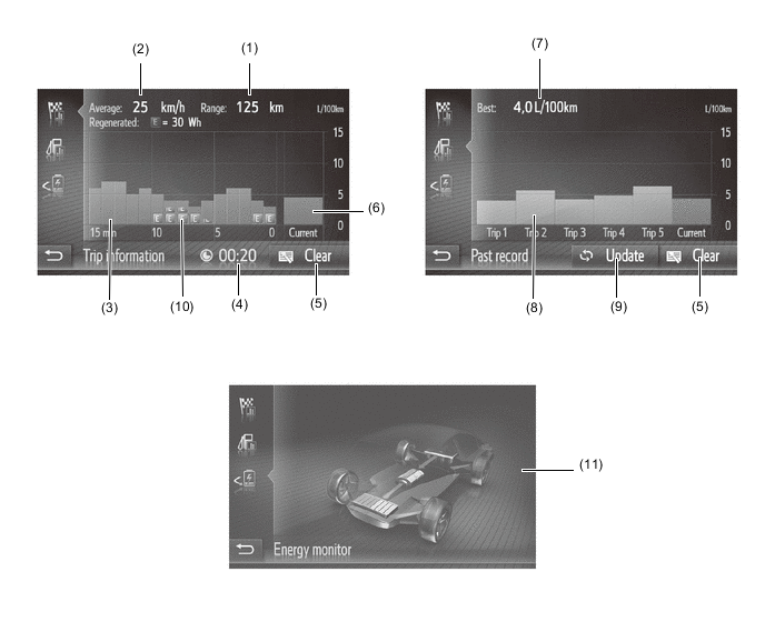
Item Outline (1) Cruising Range Displays the approximate drivable distance. (2) Average Speed Displays the value that has been calculated by the combination meter assembly, which is based on the distance driven and the time elapsed since the power switch was turned to ON. (3) Average Fuel Consumption per Minute
-
Displays the value that has been calculated by the combination meter assembly, which is based on the driven distance and the volume of fuel consumed (fuel injection signal), provided that the power switch is ON.
-
Displays the average fuel consumption for the last 15 minutes or since clear was last selected.
(4) Elapsed Time Displays the value that has been calculated by the combination meter assembly, which is based on the time elapsed since the power switch was turned to ON. (5) Clear Switch Clears all of the past information. (6) Current Fuel Consumption per Minute Displays the instantaneous (current) fuel consumption value that has been calculated by the combination meter assembly, which is based on the driven distance and the volume of fuel consumed (fuel injection signal), provided that the power switch is ON. (7) Best Fuel Consumption Displays the best (the most economical) fuel consumption per trip. (8) Average Fuel Consumption per Trip
-
Displays the current record and the last 5 average fuel consumption per trip records or the current record and those since clear was last selected.
-
Starts calculating the average fuel consumption when the average fuel consumption displayed on the combination meter assembly is reset.
(9) Update Switch
-
Restarts calculation of the average fuel consumption value.
-
Sends the average fuel consumption reset signal to the combination meter assembly to update the graph.
(10) Recovered Energy
-
Indicates the recovered energy for 1 minute with "E" symbols.
-
The recovered energy status is calculated by the hybrid vehicle control ECU.
(11) Energy Monitor Indicates the energy transmission direction, making it possible to confirm the current drive method (engine, motor or both), the power generation status of the engine and the status of regenerative energy use.
-
The State Of Charge (SOC) of the battery can be checked on the meter. The meter shows the SOC in 9-levels.
-
Displays the energy monitor status that has been calculated by the hybrid vehicle control ECU.
-
-
-
Setup Screen
-
The settings for the functions of the radio and display receiver assembly are available from the setup screen.
Component Function General Settings
-
Language: Select to change the language.
-
Volume settings: Select to set the volume for the phone/navigation.
-
Unit of measurement: Select to change the unit of measure for distance.
-
Beep: Select to set the beep sounds on/off.
-
Automatic text scrolling: Select to set the automatic text scrolling on/off. This function is not available while driving.
-
Backup stored contacts to USB: The entries stored in the "Stored" list on the "My destinations" screen and "Contacts" screen can be transferred to a USB memory.
-
Restore contact backup from USB: "vCard" formatted data can be transferred from a USB memory to this system. Transferred addresses and numbers will be stored in the "Stored" list on the "My destinations" screen and "Contacts" screen.
-
Delete all personal data: Select to delete all personal data stored in this system.
-
System information: Select to display the system information.
-
Open source information: Select to display the open source information.
Display Settings
-
Day mode: Select to set day mode on/off.
-
Screen off: Select to turn the screen off. To turn it on, press any button on the audio panel.
-
Contrast: Select to adjust the contrast of display.
-
Brightness: Select to adjust the brightness of display.
-
Camera: Select to adjust the camera display.
Audio Settings
-
Bass/Mid/Treble: Select to adjust the bass/mid/treble.
-
Balance/Fader: Select to adjust the balance/fader.
-
Automatic sound leveling: Select to set the Automatic sound leveling to low, mid, high or off.
-
Surround sound: Select to set the surround on/off.
Connectivity Settings
-
Bluetooth: Select to display a submenu for Bluetooth where you can connect phone, audio devices and internet devices via Bluetooth.
-
Wi-Fi: Select to display a submenu for Wi-Fi where you can connect internet devices via Wi-Fi.*
-
Connect me to Internet: Select to search for available internet connection methods.
-
Internet auto connection: Enable to automatically connect to internet.
-
Toyota web account: Select to add or change your Toyota web account.
Telephone Settings
-
Announce incoming messages: Select to set the incoming short message announcement function on/off.
-
Announce incoming emails: Select to set the incoming e-mail announcement function on/off.
-
Select ringtone: Select to set the desired ringtone.
-
Refresh phone book: Select to update the phone book of the connected phone manually. The updating takes place by referring to the phone book lists in the navigation/multimedia system phone.
Vehicle Settings Customizable vehicle settings can be changed.
-
*: Models with extension box (high grade type)
-
-
-
-
DIAGNOSIS
-
For details on the procedure required to enter the Service Menu screen, refer to the Repair Manual.
-