BODY STRUCTURE
-
CONSTRUCTION
-
Impact Absorbing Structure for Frontal Collision
-
A structure that ensures collision energy absorption efficiency, dissipates impact and minimizes cabin deformation during a frontal collision has been achieved.
-
The front impact energy is transferred to the front side member sub-assembly inner and spread to the rocker through the torque box front.
-
The front impact energy is transferred to the front apron to cowl side member sub-assembly and spread to the front door reinforcement sub-assembly through the MICS* bulkhead.
-
*: Minimum Intrusion Cabin System
-
The front impact energy is transferred to the front apron to cowl side member sub-assembly and spread to the roof side rails through the reinforcement in the front body pillar such as front body pillar reinforcement UPR.
-
The front impact energy is transferred to the front side member sub-assembly inner and spread to the underbody framework.
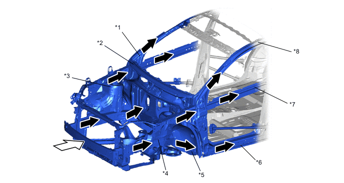
*1 Front Body Pillar Reinforcement UPR *2 MICS Bulkhead *3 Front Apron to Cowl Side Member Sub-assembly *4 Front Side Member Sub-assembly Inner *5 Torque Box Front *6 Rocker *7 Front Door Reinforcement Sub-assembly *8 Roof Side Rail 
Front Impact Energy 
Dissipate 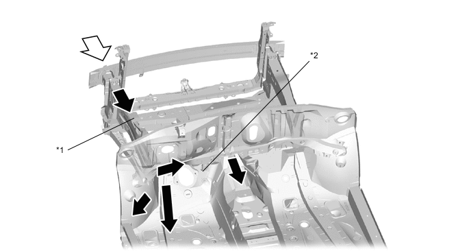
*1 Front Side Member Sub-assembly Inner *2 Underbody Framework Front Impact Energy Dissipate
-
-
-
Impact Absorbing Structure for Side Collision
-
A structure that ensures collision energy absorption efficiency, dissipates impact and minimizes cabin deformation during a side collision has been achieved.
-
Ultra high-tensile strength sheet steel (980 MPa class) and high-tensile strength sheet steel (590 MPa class) are used for each body frame part, thus ensuring strength against side collisions and achieving weight reduction and structure simplicity.
-
Ultra high-tensile strength sheet steel (980 MPa class) is used for the rocker reinforcement outer and center pillar upper hinge reinforcement No. 1.
-
High-tensile strength sheet steel (590 MPa class) is used for the roof panel reinforcement No. 1 (models with normal roof) and roof side rail outer, etc.
-
Tailored blank steel (material in which 980 Mpa, 590 MPa or 440 MPa class steel sheet was laser-welded in advance) is used for the center body pillar reinforcement outer.
-
Bulkheads (rocker panel reinforcement No. 3, main floor side member reinforcement, front floor reinforcement No. 2 and front floor cross member plate No. 3) are used inside the rocker and in the underbody below the center body pillar, thus achieving a structure which effectively transfers the impact energy during a side collision.
-
The front door side-impact protect beam sub-assembly is optimally positioned, thus achieving a structure which effectively transfers the impact load.
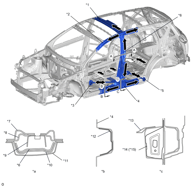
*1 Roof Panel Reinforcement No. 1 *2 Roof Side Rail Outer *3 Front Door Side-impact Protect Beam Sub-assembly *4 Rocker Reinforcement Outer *5 Rear Door Protection Beam Sub-assembly *6 Center Pillar Upper Hinge Reinforcement No. 1 *7 Center Body Pillar Inner UPR *8 Belt Anchor to Center Pillar Reinforcement LWR *9 Belt Anchor to Center Pillar Patch *10 Center Body Pillar Reinforcement Outer *11 Side Panel Outer *12 Rocker Panel Reinforcement No. 3 *13 Front Floor Cross Member Plate No. 3 *14 Main Floor Side Member Reinforcement *15 Front Floor Reinforcement No. 2 - - *a A - A Cross Section *b B - B Cross Section *c C - C Cross Section - - Side Impact Energy Dissipate -
A head impact protection structure is used. With this type of construction, if the occupant's head hits against the roof side rail, pillar and back door opening portion in reaction to a collision, the inner panel of the roof side rail and pillar collapses to help reduce the impact.
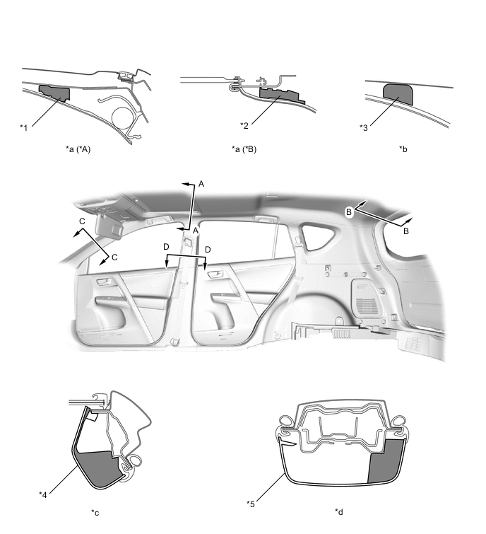
*A Models with Normal Roof *B Models with Sliding Roof *1 Roof Headlining Support *2 Roof Headlining Support No. 3 *3 EA Pad *4 Front Pillar Garnish Assembly *5 Center Pillar Garnish - - *a A - A Cross Section *b B - B Cross Section *c C - C Cross Section *d D - D Cross Section 
Energy Absorber - - -
A front door trim pad CTR is provided in the door trim to help dampen the impact applied from the side of the vehicle to the occupants.
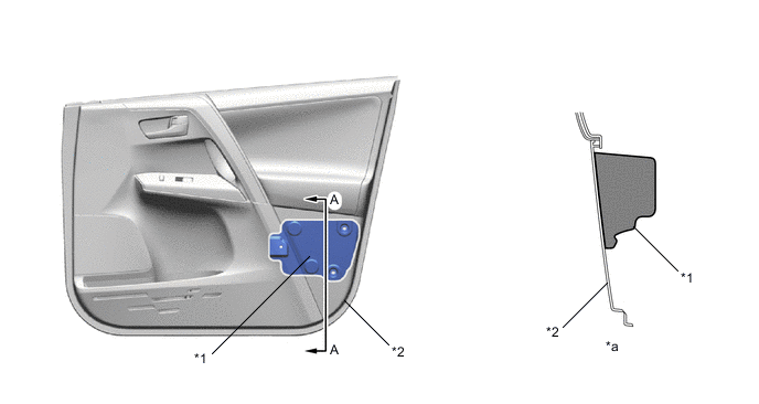
*1 Front Door Trim Pad CTR *2 Front Door Trim Board Sub-assembly *a A - A Cross Section - -
-
-
-
Impact Absorbing Structure for Rear Collision
-
A large-size rear bumper reinforcement (rear bumper reinforcement sub-assembly) is used to spread the impact energy during a rear offset collision. This distributes an impact load to the left and right rear floor side member sub-assembly front, thus suppressing cabin deformation.
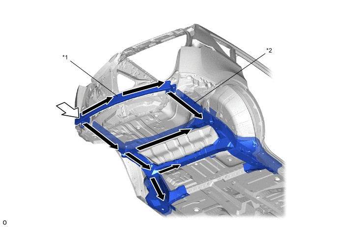
*1 Rear Bumper Reinforcement Sub-assembly *2 Rear Floor Side Member Sub-assembly Front Rear Impact Energy Dissipate
-
-
Reduction Pedestrian Head Injury
-
The following shape is used for the cowl panel sub-assembly and cowl top ventilator louver sub-assembly, thus maintaining necessary rigidity and aiming for a reduction of impact against a pedestrian in a collision with a pedestrian.
-
By reducing the rigidity of the cowl top ventilator louver sub-assembly, the counteracting force on pedestrians during a collision has been reduced. As a result, the impact on pedestrians has been reduced.
-
The rear wall of the cowl panel sub-assembly collapses like a pantograph to reduce the counteracting force on pedestrians during a collision. As a result, the impact on pedestrians has been reduced.
-
The dropout zone for the wiper pivot is ensured to allow the pivot to drop easily, thus reducing the counteracting force on pedestrians. As a result, the impact on pedestrians has been reduced.
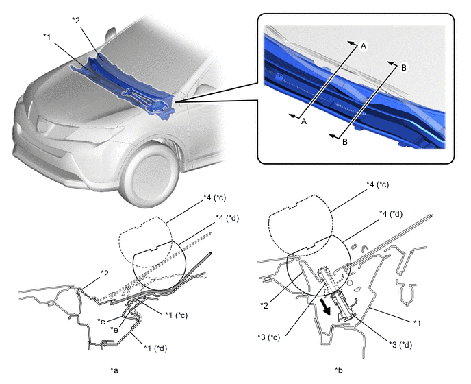
*1 Cowl Panel Sub-assembly *2 Cowl Top Ventilator Louver Sub-assembly *3 Wiper Pivot *4 Headform Impactor *a A - A Cross Section *b B - B Cross Section *c Before Collision *d After Collision *e Pantograph Structure - - -
For the front portion of the hood sub-assembly, a structure with sufficient clearance between the hood panel, hood panel reinforcement and hood lock hook is ensured. As a result, a space is made to absorb the collision impact during an accidental contact with pedestrians, thus reducing the impact on pedestrians.
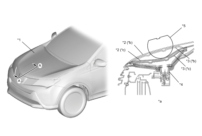
*1 Hood Sub-assembly *2 Hood Panel *3 Hood Panel Reinforcement *4 Hood Lock Hook *5 Headform Impactor - - *a A - A Cross Section *b Before Collision *c After Collision - - -
Fender brackets (fender apron retainer sub-assembly and front fender apron extension rear) are used in the joint portion of the front fender. The height of the fender bracket and the gap between the fender bracket and the fender have been optimized. Also, fold points are provided on the fender brackets. Therefore, during a collision with a pedestrian, the fender brackets absorb impact energy, with the aim of reducing the potential impact to the pedestrian's head.
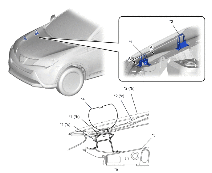
*1 Fender Apron Retainer Sub-assembly *2 Front Fender Apron Extension Rear *3 Fender Side Apron Sub-assembly *4 Headform Impactor *a A - A Cross Section *b Before Collision *c After Collision - -
-
-
Reduction Pedestrian Leg Injury
-
A pedestrian injury reduction body is used in consideration of reducing injury of a pedestrian in the case of a collision with a pedestrian. The impact absorbing structure is used on the periphery of the front bumper, thus achieving a body structure which reduces impact on pedestrian's legs, etc.
-
A front bumper energy absorber No. 2 is provided in front of the front bumper reinforcement and a front bumper absorber lower is provided in the lower portion of the radiator support sub-assembly, thus achieving a structure made to reduce the impact on pedestrian's legs during a collision.
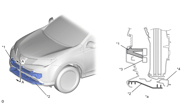
*1 Front Bumper Energy Absorber No. 2 *2 Front Bumper Absorber Lower *3 Front Bumper Reinforcement *4 Radiator Support Sub-assembly *a A - A Cross Section - -
-
-