STOP AND START SYSTEM Starter Signal Circuit
| DTC Code | DTC Name |
|---|---|
| Starter Signal Circuit |
DESCRIPTION
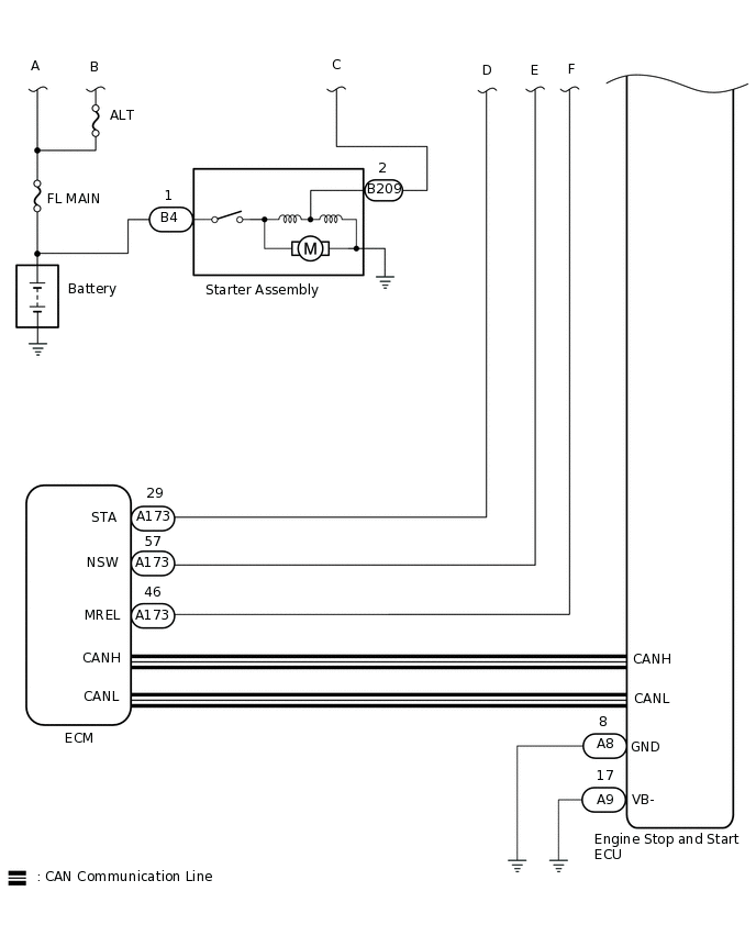
The engine stop and start ECU can activate the ST NO. 1 relay to operate the starter assembly.
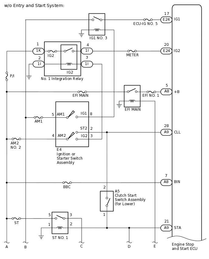
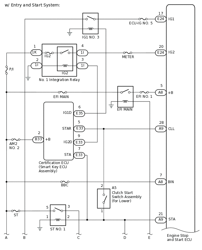
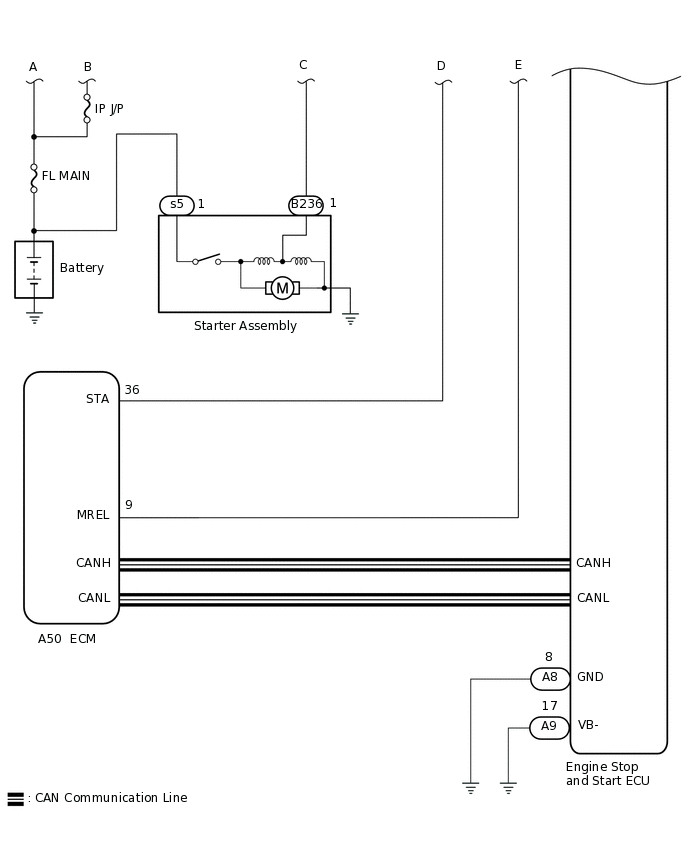
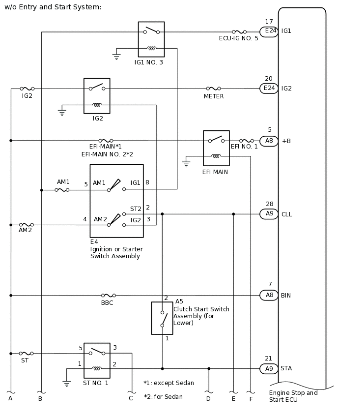
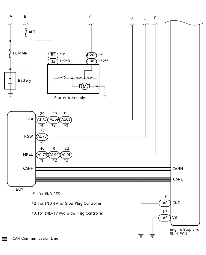
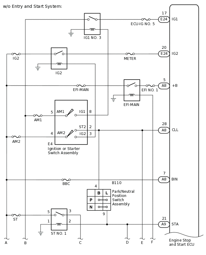
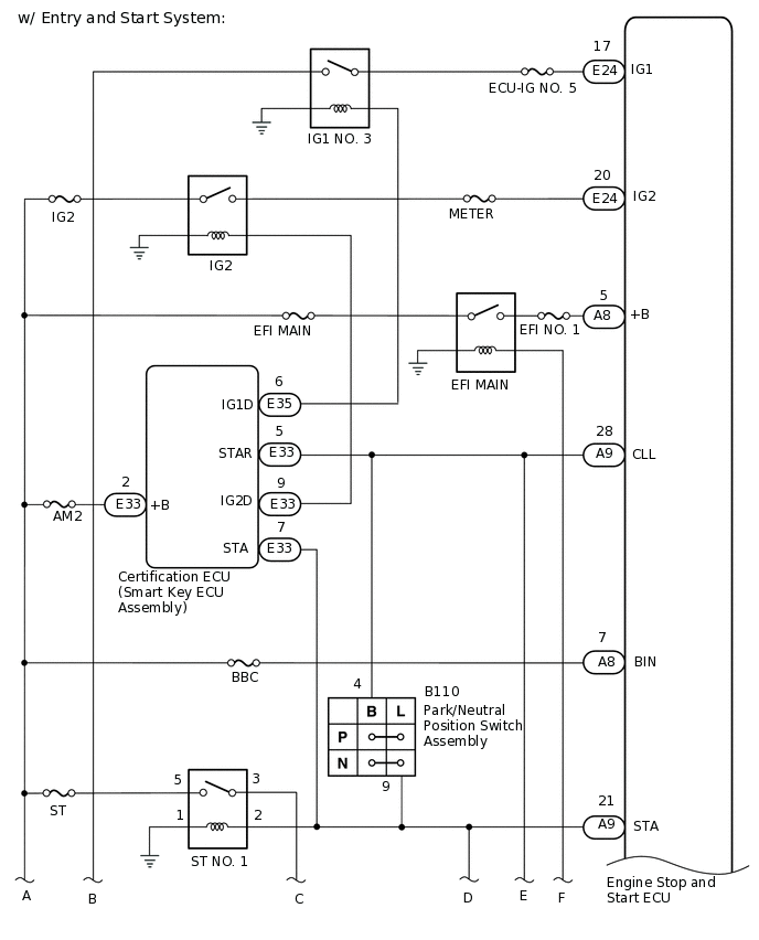
WIRING DIAGRAM
for Manual Transaxle (for 1WW)
for Manual Transaxle (except 1WW)
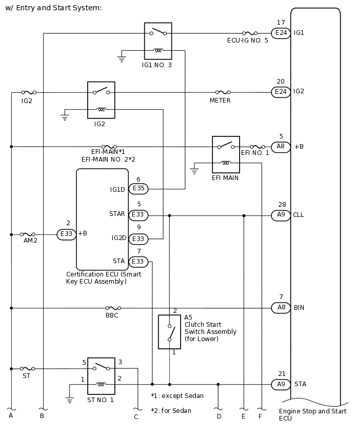
for CVT
CAUTION / NOTICE / HINT
Before replacing the engine stop and start ECU, read the number of starter operations and write it into a new engine stop and start ECU.
After replacing the engine stop and start ECU or air conditioning amplifier assembly, reset and perform learning of the air conditioning information in the engine stop and start ECU.
After replacing the engine stop and start ECU or airbag sensor assembly, clear and calibrate the deceleration sensor zero point in the engine stop and start ECU.
After replacing the starter assembly, perform initialization of the number of starter operations stored in the engine stop and start ECU.
When the starter assembly is replaced, "ST NO. 1 relay" must be also replaced.
Inspect the fuses for circuits related to this system before performing the following procedure.
PROCEDURE
CHECK CRANKING
Turn the ignition switch to START and check that the engine cranks.
Result
Result
Proceed to
Engine cranks
A
Engine does not crank
B
B PERFORM ACTIVE TEST USING GTS (STARTER)Click here
PERFORM ACTIVE TEST USING GTS (STARTER)
Connect the GTS to the DLC3.
Turn the ignition switch to ON.
Turn the GTS on.
Enter the following menus: Powertrain / Stop and Start / Active Test / Starter.
Powertrain > Stop and Start > Active Test
Tester Display
Starter
Check whether the engine cranks while the Active Test "Starter" is being performed.
Note:The Active Test "Starter" is stopped automatically 3 seconds after the starter assembly begins operating.
Standard
Engine cranks
Result
Proceed to
OK
NG
CHECK HARNESS AND CONNECTOR (ENGINE STOP AND START ECU POWER SOURCE CIRCUIT)
-
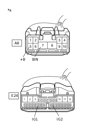
*a
Front view of wire harness connector
(to Engine Stop and Start ECU)
Disconnect the A8 and E24 engine stop and start ECU connectors.
Measure the voltage according to the value(s) in the table below.
Standard Voltage
Tester Connection
Condition
Specified Condition
A8-7 (BIN) - Body ground
Always
9.5 to 14 V
Turn the ignition switch to ON.
Measure the voltage according to the value(s) in the table below.
Standard Voltage
Tester Connection
Condition
Specified Condition
A8-5 (+B) - Body ground
Ignition Switch ON
9.5 to 14 V
E24-17 (IG1) - Body ground
Ignition Switch ON
9.5 to 14 V
E24-20 (IG2) - Body ground
Ignition Switch ON
9.5 to 14 V
Result
Proceed to
OK
NG
NG REPAIR OR REPLACE HARNESS OR CONNECTOR
-
CHECK HARNESS AND CONNECTOR (ENGINE STOP AND START ECU - BODY GROUND)
Disconnect the A8 and A9 engine stop and start ECU connectors.
Measure the resistance according to the value(s) in the table below.
Standard Resistance
Tester Connection
Condition
Specified Condition
A8-8 (GND) - Body ground
Always
Below 1 Ω
A9-17 (VB-) - Body ground
Always
Below 1 Ω
Result
Proceed to
OK
NG
NG REPAIR OR REPLACE HARNESS OR CONNECTOR
PERFORM ACTIVE TEST USING GTS (STARTER)
Connect the GTS to the DLC3.
Turn the ignition switch to ON.
Turn the GTS on.
Enter the following menus: Powertrain / Stop and Start / Active Test / Starter.
Powertrain > Stop and Start > Active Test
Tester Display
Starter
Check whether the engine cranks while the Active Test "Starter" is being performed.
Note:The Active Test "Starter" is stopped automatically 3 seconds after the starter assembly begins operating.
Standard
Engine cranks
Result
Result
Proceed to
Engine cranks
A
Engine does not crank
B
B CHECK HARNESS AND CONNECTOR (ST NO. 1 RELAY - BODY GROUND)Click here
CONFIRM MODEL
Choose the model to be inspected.
Result
Result
Proceed to
for Manual Transaxle
A
for CVT
B
B READ VALUE USING GTS (NEUTRAL SWITCH)Click here
READ VALUE USING GTS (CLUTCH LOWER SW)
Connect the GTS to the DLC3.
Turn the ignition switch to ON.
Turn the GTS on.
Enter the following menus: Powertrain / Stop and Start / Data List / Clutch Lower SW
In accordance with the display on the GTS, read the Data List.
Powertrain > Stop and Start > Data List
Tester Display
Clutch Lower SW
OK
Tester Display
Condition
Normal Condition
Clutch Lower SW
Fully Depressed
ON
Fully Released
OFF
Result
Result
Proceed to
Data Monitor display is not within standards
A
Data Monitor display is within standards (w/o Entry and Start System)
B
Data Monitor display is within standards (w/ Entry and Start System)
C
B INSPECT IGNITION OR STARTER SWITCH ASSEMBLYClick here
C CHECK HARNESS AND CONNECTOR (CERTIFICATION ECU (SMART KEY ECU ASSEMBLY) - ENGINE STOP AND START ECU)Click here
INSPECT CLUTCH START SWITCH ASSEMBLY (FOR LOWER)
Inspect the clutch start switch assembly (for lower).
Result
Result
Proceed to
OK ( w/o Smart Entry and Star System)
A
OK ( w/ Smart Entry and Star System)
B
NG
C
B CHECK HARNESS AND CONNECTOR (CERTIFICATION ECU (SMART KEY ECU ASSEMBLY) - ST NO. 1 RELAY)Click here
CHECK HARNESS AND CONNECTOR (IGNITION OR STARTER SWITCH ASSEMBLY - ST NO. 1 RELAY)
Disconnect the A9 engine stop and start ECU connectors.
Disconnect the E4 ignition or starter switch assembly connector.
Remove the ST NO. 1 relay from engine room relay block and junction block assembly.
Measure the resistance according to the value(s) in the table below.
Standard Resistance
Tester Connection
Condition
Specified Condition
E4-2 (ST2) - ST NO. 1 relay terminal 2
Fully Depressed
Below 1 Ω
E4-2 (ST2) - ST NO. 1 relay terminal 2
Fully Released
10 kΩ or higher
Result
Proceed to
OK
NG
NG REPAIR OR REPLACE HARNESS OR CONNECTOR
CHECK HARNESS AND CONNECTOR (CERTIFICATION ECU (SMART KEY ECU ASSEMBLY) - ST NO. 1 RELAY)
Disconnect the E33 certification ECU (smart key ECU assembly) connector.
Remove the ST NO. 1 relay from engine room relay block and junction block assembly.
Measure the resistance according to the value(s) in the table below.
Standard Resistance
Tester Connection
Condition
Specified Condition
E33-5 (STAR) - ST NO. 1 relay terminal 2
Fully Depressed
Below 1 Ω
E33-5 (STAR) - ST NO. 1 relay terminal 2
Fully Released
10 kΩ or higher
Result
Proceed to
OK
NG
NG REPAIR OR REPLACE HARNESS OR CONNECTOR
INSPECT IGNITION OR STARTER SWITCH ASSEMBLY
Inspect the ignition or starter switch assembly.
for 1ND-TV:Click here
for 1WW:Click here
for 8NR-FTS:Click here
Result
Proceed to
OK
NG
NG REPLACE IGNITION OR STARTER SWITCH ASSEMBLY
CHECK HARNESS AND CONNECTOR (IGNITION OR STARTER SWITCH ASSEMBLY - BATTERY)
Disconnect the E4 ignition or starter switch assembly connector.
-
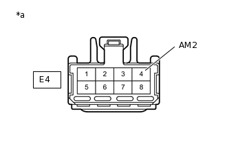
*a
Front view of wire harness connector
(to Ignition or Starter Switch Assembly)
Measure the voltage according to the value(s) in the table below.
Standard Voltage
Tester Connection
Condition
Specified Condition
E4-4 (AM2) - Body ground
Always
9.5 to 14 V
Result
Proceed to
OK
NG
NG REPAIR OR REPLACE HARNESS OR CONNECTOR
CHECK HARNESS AND CONNECTOR (IGNITION OR STARTER SWITCH ASSEMBLY - CLUTCH START SWITCH ASSEMBLY (FOR LOW))
Disconnect the E4 ignition or starter switch assembly connector.
Disconnect the A9 engine stop and start ECU connector.
Disconnect the A173 ECM connector. *
Disconnect the A5 clutch start switch assembly (for low) connector.
Measure the resistance according to the value(s) in the table below.
Standard Resistance
Tester Connection
Condition
Specified Condition
E4-2 (ST2) - A5-2
Always
Below 1 Ω
E4-2 (ST2) - Body ground
Always
10 kΩ or higher
A5-2 - Body ground
Always
10 kΩ or higher
A9-28 (CLL) - Body ground
Always
10 kΩ or higher
A173-57(NSW) - Body ground*
Always
10 kΩ or higher
*: for 8NR-FTS
Result
Proceed to
OK
NG
NG REPAIR OR REPLACE HARNESS OR CONNECTOR
CHECK HARNESS AND CONNECTOR (CERTIFICATION ECU (SMART KEY ECU ASSEMBLY) - ENGINE STOP AND START ECU)
Disconnect the A5 clutch start switch assembly (for low) connector.
Disconnect the E33 certification ECU (smart key ECU assembly) connector.
Disconnect the A9 engine stop and start ECU connector.
Measure the resistance according to the value(s) in the table below.
Standard Resistance
Tester Connection
Condition
Specified Condition
E33-5 (STAR) - A9-28 (CLL)
Always
Below 1 Ω
E33-5 (STAR) - Body ground
Always
10 kΩ or higher
A9-28 (CLL) - Body ground
Always
10 kΩ or higher
Result
Proceed to
OK
NG
NG REPAIR OR REPLACE HARNESS OR CONNECTOR
CHECK CERTIFICATION ECU (SMART KEY ECU ASSEMBLY) (STAR SIGNAL)
-
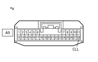
*a
Front view of wire harness connector
(to Engine Stop and Start ECU)
Disconnect the A9 engine stop and start ECU connector.
Measure the voltage according to the value(s) in the table below.
Standard Voltage
Tester Connection
Condition
Specified Condition
A9-28 (CLL) - Body ground
Engine start
9.5 to 14 V
Result
Proceed to
OK
NG
-
READ VALUE USING GTS (NEUTRAL SWITCH)
Connect the GTS to the DLC3.
Turn the ignition switch to ON.
Turn the GTS on.
Enter the following menus: Powertrain / Stop and Start / Data List / Neutral Switch.
In accordance with the display on the GTS, read the Data List.
Powertrain > Stop and Start > Data List
Tester Display
Neutral Switch
OK
Tester Display
Condition
Normal Condition
Neutral Switch
Shift lever in P or N
ON
Shift lever not in P or N
OFF
Result
Result
Proceed to
Data Monitor display is not within standards
A
Data Monitor display is within standards (w/o Entry and Start System)
B
Data Monitor display is within standards (w/ Entry and Start System)
C
B INSPECT IGNITION OR STARTER SWITCH ASSEMBLYClick here
C CHECK HARNESS AND CONNECTOR (CERTIFICATION ECU (SMART KEY ECU ASSEMBLY) - ENGINE STOP AND START ECU)Click here
INSPECT PARK/NEUTRAL POSITION SWITCH ASSEMBLY
Inspect the park/neutral position switch assembly.
Result
Result
Proceed to
OK ( w/o Smart Entry and Star System)
A
OK ( w/ Smart Entry and Star System)
B
NG
C
B CHECK HARNESS AND CONNECTOR (CERTIFICATION ECU (SMART KEY ECU ASSEMBLY) - ST NO. 1 RELAY)Click here
CHECK HARNESS AND CONNECTOR (IGNITION OR STARTER SWITCH ASSEMBLY - ST NO. 1 RELAY)
Disconnect the A9 engine stop and start ECU connectors.
Disconnect the E4 ignition or starter switch assembly connector.
Remove the ST NO. 1 relay from engine room relay block and junction block assembly.
Measure the resistance according to the value(s) in the table below.
Standard Resistance
Tester Connection
Condition
Specified Condition
E4-2 (ST2) - ST NO. 1 relay terminal 2
Fully Depressed
Below 1 Ω
E4-2 (ST2) - ST NO. 1 relay terminal 2
Fully Released
10 kΩ or higher
Result
Proceed to
OK
NG
NG REPAIR OR REPLACE HARNESS OR CONNECTOR
CHECK HARNESS AND CONNECTOR (CERTIFICATION ECU (SMART KEY ECU ASSEMBLY) - ST NO. 1 RELAY)
Disconnect the E33 certification ECU (smart key ECU assembly) connector.
Remove the ST NO. 1 relay from engine room relay block and junction block assembly.
Measure the resistance according to the value(s) in the table below.
Standard Resistance
Tester Connection
Condition
Specified Condition
E33-5 (STAR) - ST NO. 1 relay terminal 2
Shift lever in P or N
Below 1 Ω
E33-5 (STAR) - ST NO. 1 relay terminal 2
Shift lever not in P or N
10 kΩ or higher
Result
Proceed to
OK
NG
NG REPAIR OR REPLACE HARNESS OR CONNECTOR
INSPECT IGNITION OR STARTER SWITCH ASSEMBLY
Inspect the ignition or starter switch assembly.
for 1ND-TV:Click here
for 1WW:Click here
for 8NR-FTS:Click here
Result
Proceed to
OK
NG
NG REPLACE IGNITION OR STARTER SWITCH ASSEMBLY
CHECK HARNESS AND CONNECTOR (IGNITION OR STARTER SWITCH ASSEMBLY - BATTERY)
Disconnect the E4 ignition or starter switch assembly connector.
-
*a
Front view of wire harness connector
(to Ignition or Starter Switch Assembly)
Measure the voltage according to the value(s) in the table below.
Standard Voltage
Tester Connection
Condition
Specified Condition
E4-4 (AM2) - Body ground
Always
9.5 to 14 V
Result
Proceed to
OK
NG
NG REPAIR OR REPLACE HARNESS OR CONNECTOR
CHECK HARNESS AND CONNECTOR (IGNITION OR STARTER SWITCH ASSEMBLY - PARK/NEUTRAL POSITION SWITCH ASSEMBLY)
Disconnect the E4 ignition or starter switch assembly connector.
Disconnect the A9 engine stop and start ECU connector.
Disconnect the A173 ECM connector.
Disconnect the B110 park/neutral position switch assembly connector.
Measure the resistance according to the value(s) in the table below.
Standard Resistance
Tester Connection
Condition
Specified Condition
E4-2 (ST2) - B110-4 (B)
Always
Below 1 Ω
E4-2 (ST2) - Body ground
Always
10 kΩ or higher
B110-4 (B) - Body ground
Always
10 kΩ or higher
A9-28 (CLL) - Body ground
Always
10 kΩ or higher
A173-57 (NSW) - Body ground
Always
10 kΩ or higher
Result
Proceed to
OK
NG
NG REPAIR OR REPLACE HARNESS OR CONNECTOR
CHECK HARNESS AND CONNECTOR (CERTIFICATION ECU (SMART KEY ECU ASSEMBLY) - ENGINE STOP AND START ECU)
Disconnect the B110 park/neutral position switch assembly connector.
Disconnect the E33 certification ECU (smart key ECU assembly) connector.
Disconnect the A9 engine stop and start ECU connector.
Measure the resistance according to the value(s) in the table below.
Standard Resistance
Tester Connection
Condition
Specified Condition
E33-5 (STAR) - A9-28 (CLL)
Always
Below 1 Ω
E33-5 (STAR) - Body ground
Always
10 kΩ or higher
A9-28 (CLL) - Body ground
Always
10 kΩ or higher
Result
Proceed to
OK
NG
NG REPAIR OR REPLACE HARNESS OR CONNECTOR
CHECK CERTIFICATION ECU (SMART KEY ECU ASSEMBLY) (STAR SIGNAL)
-
*a
Front view of wire harness connector
(to Engine Stop and Start ECU)
Disconnect the A9 engine stop and start ECU connector.
Measure the voltage according to the value(s) in the table below.
Standard Voltage
Tester Connection
Condition
Specified Condition
A9-28 (CLL) - Body ground
Engine start
9.5 to 14 V
Result
Proceed to
OK
NG
-
CHECK HARNESS AND CONNECTOR (ST NO. 1 RELAY - BODY GROUND)
Remove the ST NO. 1 relay from engine room relay block and junction block assembly.
Measure the resistance according to the value(s) in the table below.
Standard Resistance
Tester Connection
Condition
Specified Condition
ST NO. 1 relay terminal 2 - Body ground
Always
Below 1 Ω
Result
Proceed to
OK
NG
NG REPAIR OR REPLACE HARNESS OR CONNECTOR
CHECK HARNESS AND CONNECTOR (ENGINE STOP AND START ECU - ST NO. 1 RELAY)
Disconnect the E33 certification ECU (smart key ECU assembly) connector. (w/ Entry and Start System)
Disconnect the A5 clutch start switch assembly (for lower) connector. (for Manual Transaxle)
Disconnect the B110 park/neutral position switch assembly connector. (for CVT)
Disconnect the A9 engine stop and start ECU connector.
Remove the ST NO. 1 relay from engine room relay block and junction block assembly.
Measure the resistance according to the value(s) in the table below.
Standard Resistance
Tester Connection
Condition
Specified Condition
A9-21 (STA) - ST NO. 1 relay terminal 2
Always
Below 1 Ω
A9-21 (STA) - Body ground
Always
10 kΩ or higher
ST NO. 1 relay terminal 2 - Body ground
Always
10 kΩ or higher
Result
Proceed to
OK
NG
NG REPAIR OR REPLACE HARNESS OR CONNECTOR
INSPECT STARTER ASSEMBLY
Inspect the starter assembly.
for 1ND-TV:Click here
for 1WW:Click here
for 8NR-FTS, CVT:Click here
for 8NR-FTS, Manual Transaxle:Click here
Result
Proceed to
OK
NG
NG REPLACE STARTER ASSEMBLY
for 1ND-TV:Click here
for 1WW:Click here
for 8NR-FTS, CVT:Click hereClick here
for 8NR-FTS, Manual Transaxle:Click hereClick here